Learning for later
I was invited to iMal on a 10 day mini residency, mainly to learn how to use the facilities as preparation for a longer project next year. I would have loved to come for a bit longer, but other comittments force me to be very quick and efficient here. I should explain that I have no previous knowledge of 3d modelling and production, but that I am used to graphic software like GIMP and Photoshop, and that I am a confident sculptor and builder, so I have much knowledge of materials and processes in general.
Is it at all possible to learn 3d making in 10 days? I came with the idea that the best way to learn is to try to do real projects, so I brought with me some needs, ranging from very basic to quicte complicated. My feeling is that a series of courses or tutorials might make you believe you have the practical knowledge, but only if you manage to go outside of what the tutorial has covered can you claim to have practical knowledge.
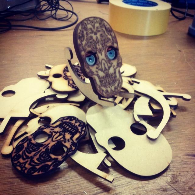
I started by using the laser cutter, which I was told is the simplest machine. For this I only needed to use 2d software, which very much simplified the process. I used Inkscape, which is a free layout program, and quickly made some small signs and name tags. As soon as I wanted to do something more complicated, I ran into resistance however. I wanted to use a bitmap image from the web as a rough sketch for a design, and found it infuriatingly hard to use the trace bitmap function in Inkscape. The solution was to combine several softwares. I find this to often be the case. The one product can only achieve what the designers of it thought you might want to do, but when you, as a creative person, try to stretch the limits, you have to start using several softwares.
I imported the bitmap in GIMP. Used color selection to pick out the parts I wanted to use, then exported these as png files with outlines with a stroke of 2px on transparent background. Don't try to export the paths directly. I tried that first of course, but it didn't work. With very simple drawings I could now get the trace bitmap function in Inkscape to perform well. It still created a series of double parallell paths (one on each side of the stroke) which I had to clean up in the proprietary laser cutter software.
I also learned that designing in the computer still means a lot of trial and error when you get the parts in your hand and they don't really fit or work as you thought they would.
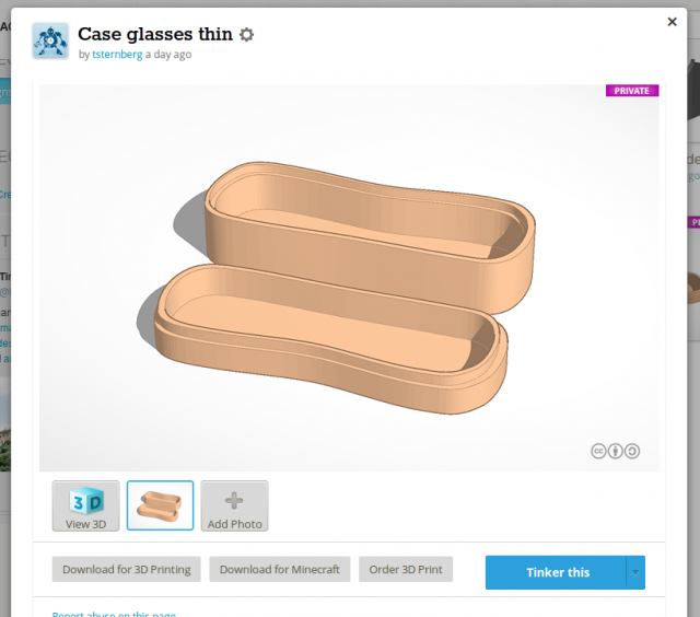
After this I wanted to try my hands on 3d printing. I spent two days getting increasingly frustrated with the free cad software Freecad. I am sure it is amazing and you can do tons of stuff with it, once you know how to use it, but I'm sorry to say that the user interface isn't very intuitive and takes a lot of focus and time to gte around. Maybe it's super easy for the maths students who designed it, but for a hands-on person like me, it just made me impatient. Blender on the other hand, struck me as much more well designed and user friendly, but in its sheer scale just a task for later on. I will definitel learn Blender for my 3d jobs, but for that I need more than a few days. My solution came in the form of the browser based Tinkercad. Very limited and very simple. In a few hours, I was happily designing away and making printable objects. My first goal was to make a snug case for my sun glasses so that they don't constantly break and bend in my pockets. It seemed limited at first, but if one uses the import feature in Tinkercad, one can take advantage of much better tools for designing bezier curves and such in Inkscape or another program. For my first attempt, I used a bezier curve that I lifted up into a simple case, with a very flat top and bottom.
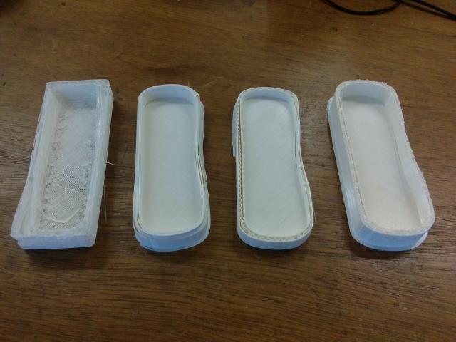
Unfortunately, this didn't print very well. I did several attempts, as you can see below, with slightly tweeked settings, but none worked well. The problem, as you can see, was that the long walls didn't connect to the base plate, and also that the several layers of the walls didn't connect well to each other along the long, straight runs. They sandwiched without gluing and thus formed a loose collection of thin sheets that didn't make a good wall. I stopped all prints before finish. I think this happened because the printer itself is slightly old and maybe needs to be recalibrated. However, this just demonstrates that 3d printing is a physical process in real life as well as a virtual design task. Sharp edges and corners demand a printer with perfect calibration, which in a real world obeying the second law of thermodynamics, you will almost never ever find! So, better to design for printers with slightly off calibration.
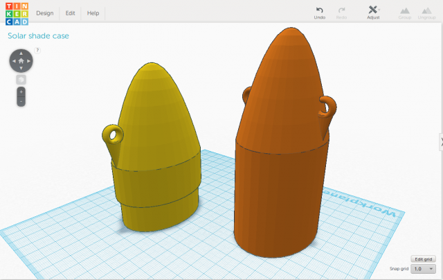
I was told that in a slightly curved shape the layers would be more likely to slightly overlap and thus stick to each other. This meant I had to radically alter the design of my case for sunglasses, also taking into consideration several more things I had realized about how the printer is actually putting the plastic together. Mainly that nothing can hang in free air (like a balcony) since the printer will struggle to create the first couple of layers. Below, my imporved design, this time made entirely out of Tinkercad shapes.
So, in this design the case looks more like one of all these soft shaped high risers that were built around the world some 10 years ago (I guess about the time that cad software made this kind of design possible). The hooks and eyelet are my design for a lock. I will thread a rubber band through the eyelet and hook both ends into the hooks to keep the two case parts together.
Info
Date: July 2016
Last updated: July 2016


