Half quadcopter
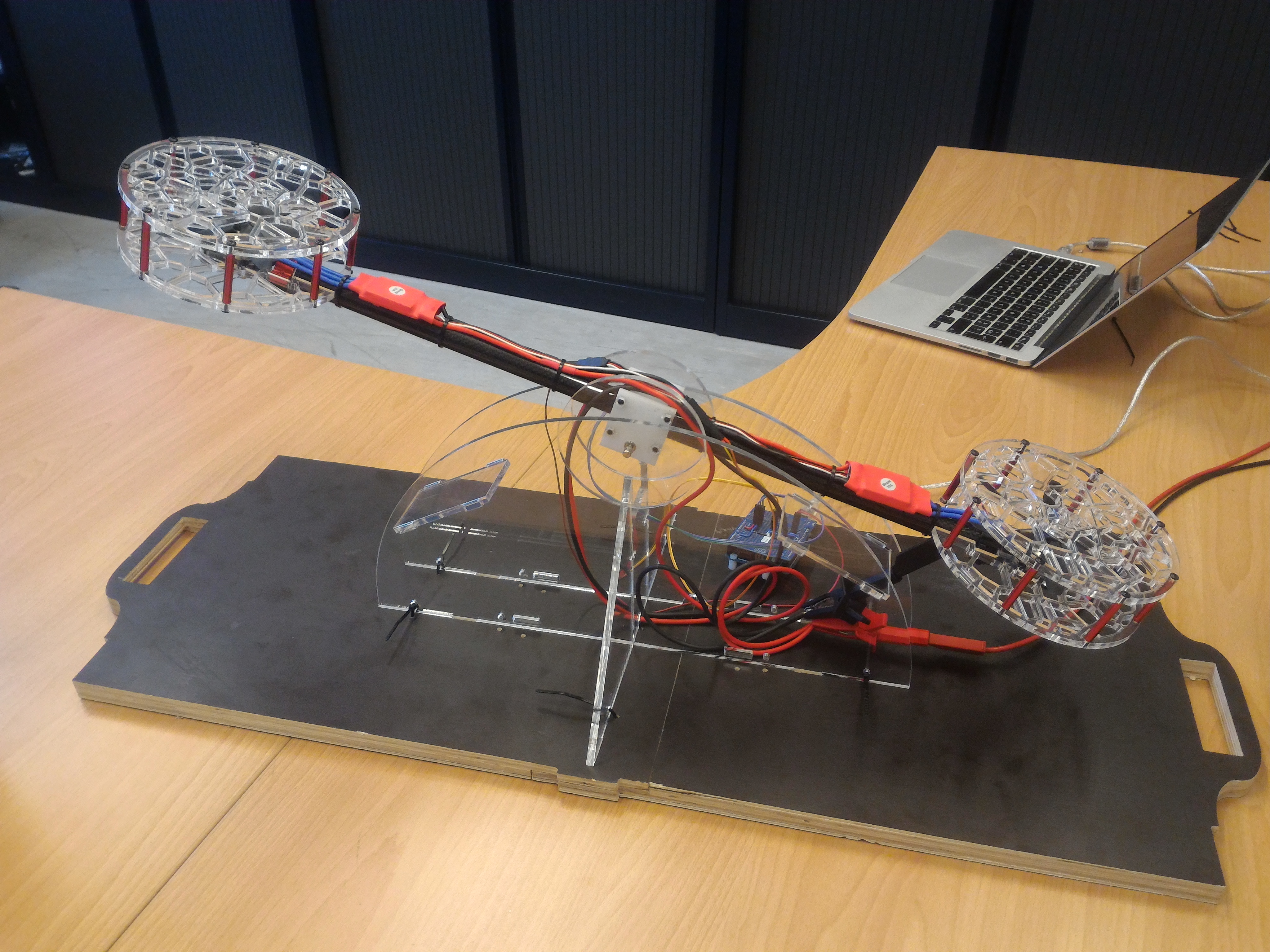
The goal is to build a half quadcopter (tandem rotor) to serve as an exercise in a framework of a control theory course, where a controller would have to be designed to perform the longitudinal attitude (pitch) control of the (half) quadcopter. The challenge of the construction is to minimize the friction at the rotation axis of the boom, mainly coming from the cables, in order to minimize demping of the system. Notice that it is not meant to be able to fly, as that would turn the exercise session in some kind of airshow, distracting the students...
But why a half quadcopter? First, it is easier to tackle the friction issue with a half quadcopter. Second, recovering the impulse response of the system is easier if there is no orthogonal axis (although in theory totally decoupled) to interfere with. Why not a "real" quadcopter? Well, the device is meant to be used to illustrate a control theory course. So, one wants students to first estimate the parameters of the system, design a controller, implement the controller (in "real time" on an arduino) and then verify that the actual measured behaviour matches that predicted in the design phase. With a real quadcopter, identifying the parameters of the quadcopter without a functioning controller would be challenging.
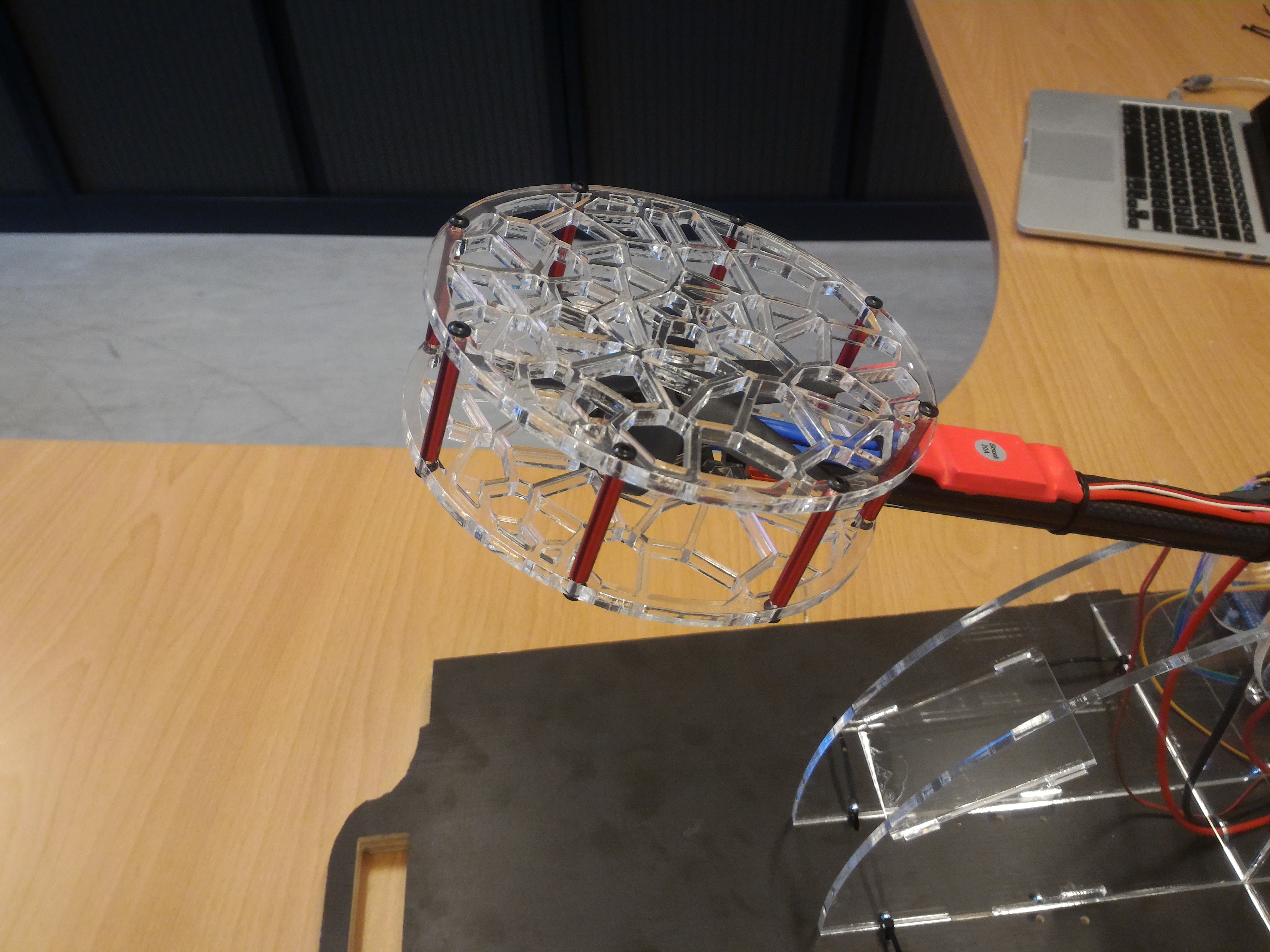
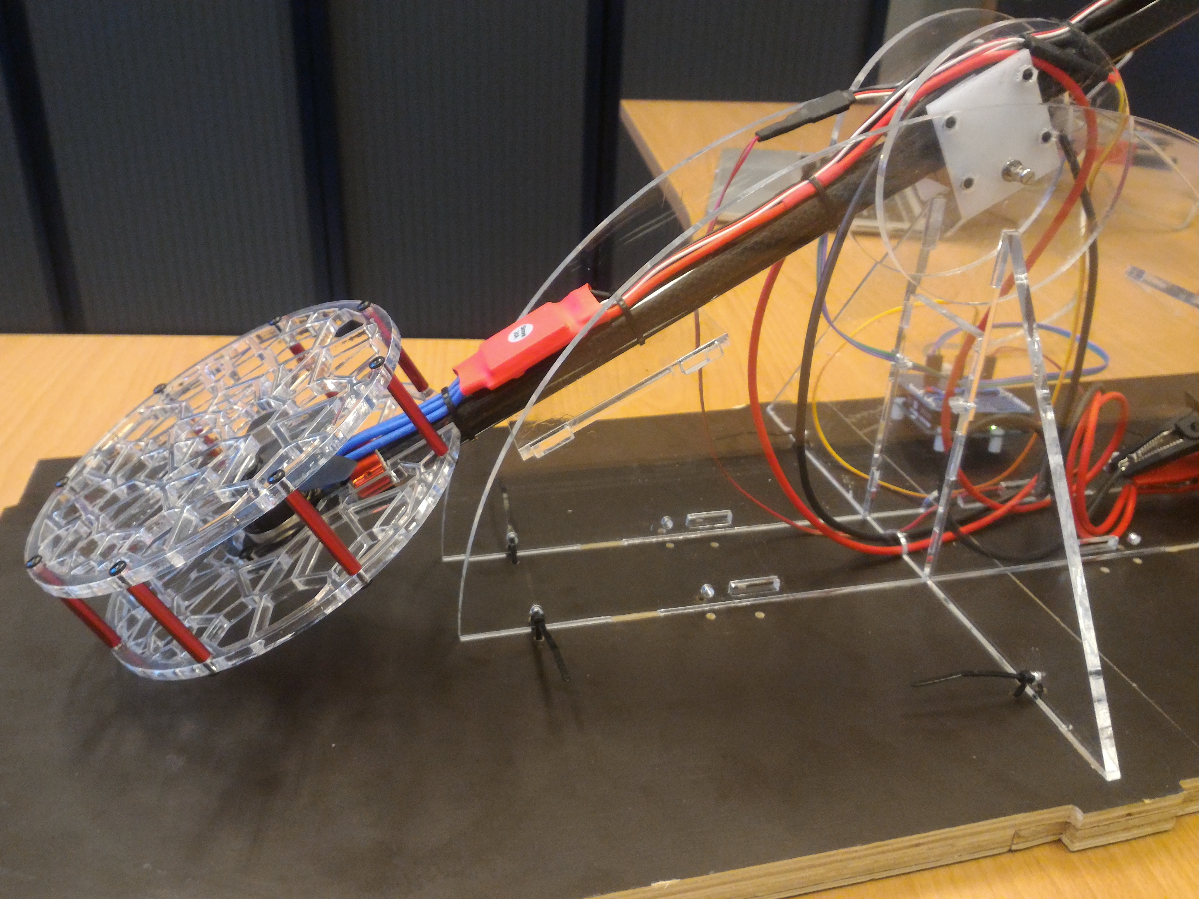
The support structure is built out of 5mm plexiglass (PMMA) cut with the laser cutter and is fastened to a 18mm multiplex plate milled on the CNC. The main boom of the half quadcopter is a 12mm carbon tube. The motors and the speed controllers are quadcopter hardware. The disk protecting the propellers (or better, protecting the finger of the students from the propellers) are also made out of laser-cut 5mm plexiglass. The holes consists of voronoï cells just because it can.
The sensor is an angle sensor functionning exactly like a potentiometer but without the friction and the wear. It is connected to one of the analog inputs of an arduino. Similarly, the two ESCs are connected to two digital PWM pins of the arduino. At full power, under 12V, one ESC (and its motor) would draw more than 3A and generate really a lot of lift. This large amount of lift helps make the residual friction negligible.
The ESC library is used to drive the ESCs. The same library is used to calibrate each ESCs.
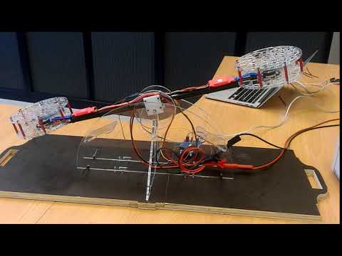
The video illustrates what happens when a proportional controller is used in the feedback loop. And, indeed and as expected, the system with a proportional feedback proves to be unstable... The design of an appropriate controller is left as an exercise to the reader.
Gallery

Videos
Info
Date: August 2018
Last updated: August 2018