CNC Milling: iMAL High-Z S-720
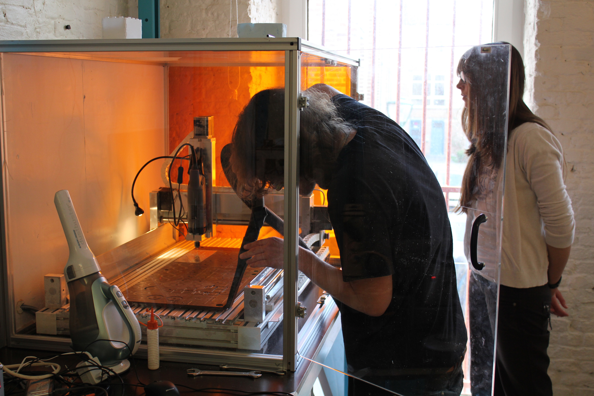
iMAL CNC routing/milling/engraving machine arrived in January 2012: it's a High-Z S-720 from German manufacturer cnc-step.com.
It's a 3 axis machine with a working area of 720x420mm (and 110mm in height). It is equipped with a Kress 1050W (10.000-30.000 rpm) spindle. We have a first set of tools (mills, drills) to cut and sculpt wood, plastic or soft metal (e.g. aluminium) and engrave PCB. The machine can be expanded to 4 axis and equipped with more powerful spindle for working harder material.
Softwares
A dedicated PC (Win XP) is configured with various softwares to generate tool paths (NC files = machine gcode instructions) from 2d and 3d designs. Besides the basic softwares supplied by the manufacturer (Win-PC NC and ConstructCAM), two softwares have been acquired:
- DeskProto : a 3d CAM (Computer Aided Manufacturing) program to generate NC files (gcode CNC machine instructions) from 3d files (e.g. DXL or STL formats). Demo version can be downloaded from www.deskproto.com
- Galaad: a 2d technical drawing and CAM software. A demo version with complete manual is available in English and in French from www.galaad.net. A module (Percival) is also supplied for PCB (Printed Circuit Board) engraving.
Sometimes, to machine an object, it is easier to think in 3d (mainly if you already have a 3d model or have skills in 3d modeling). But for many projects (or if you do not have any experience in 3d modeling), you can machine your object as a series of 2d operations...
Introduction:
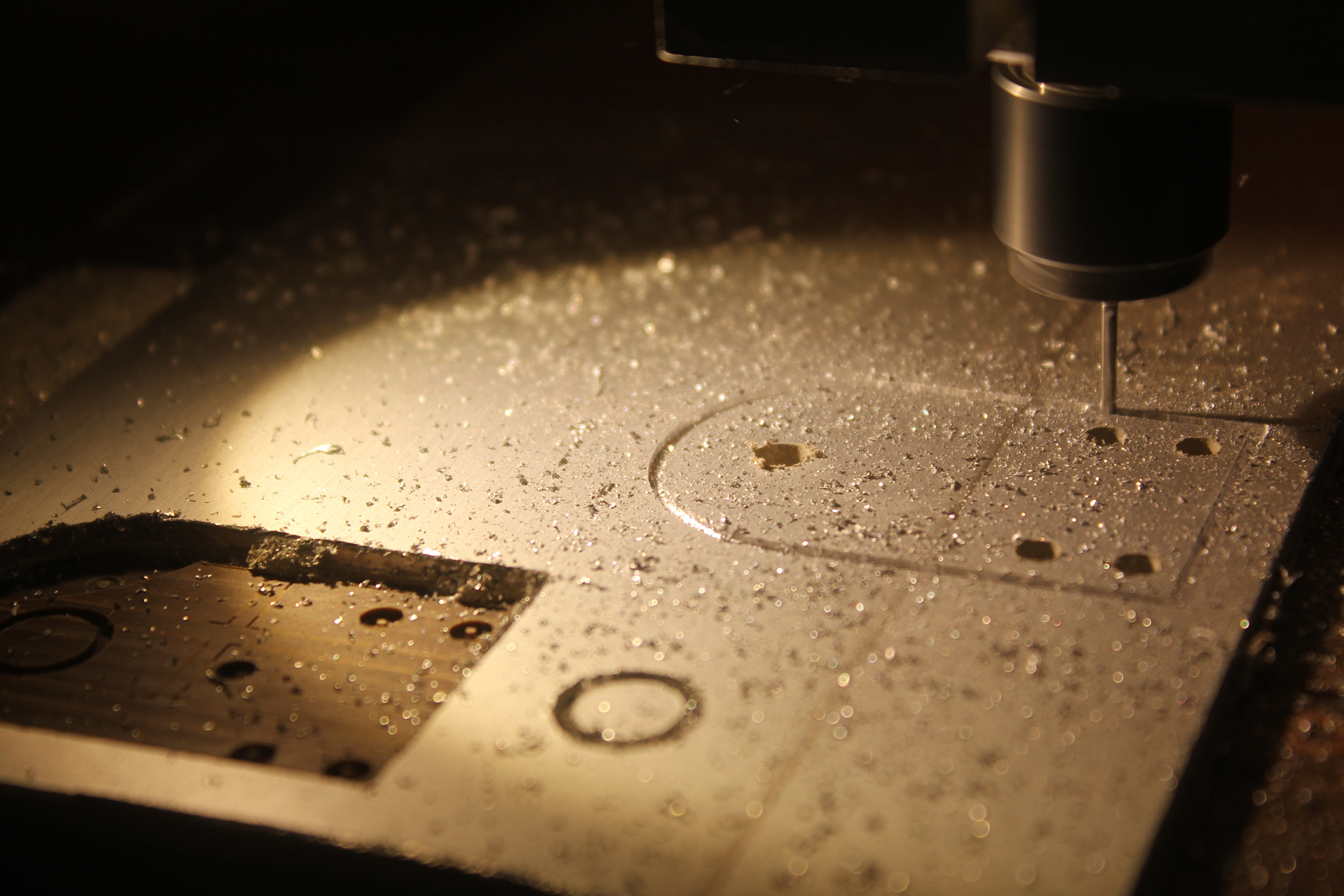
The CNC-Milling Machine is a computer-controlled machine for cutting various materials, such as wood, composites, aluminum, plastics, and foams. It uses a vertical mill with the ability to move the spindle vertically in synchrony along the X/Y/Z-axis.
Milling is the most common form of machining, a material removal process, which can create a variety of features on a part by cutting away the unwanted material. The milling process requires a milling machine, workpiece, fixture, and cutter. The workpiece is a piece of pre-shaped material that is secured to the fixture, which itself is attached to a platform inside the milling machine. The cutter is a cutting tool with sharp teeth that is also secured in the milling machine and rotates at high speeds. By moving the rotating cutter into the workpiece, material is cut away from this workpiece in the form of small chips to create the desired shape.
Milling is typically used to produce parts that are not axially symmetric and have many features, such as holes, slots, pockets, and even three-dimensional surface contours. Parts often include custom designed prototypes.
Basic Steps (using Deskproto and WIN-PC NC)
Create Geometry
Try
to be familiar ahead of time with the types of toolpaths you will use, and
generate geometry accordingly.
Prior to tooling in Deskproto, your geometry
must be scaled to the size you want your final model to be (1:1). When your
file is scaled, positioned, and ready for export, be sure the geometry is
valid.
When
you export the geometry from your favorite 3D CAD (Computer Aided Design) software, use the .stl or
.dfx file formats.
Import Geometry and Create Toolpaths
Deskproto imports 3D geometries from dfx and stl files. It is a CAM (Computer Aided Manufacturing) package specifically designed for milling 3D objects. At startup it offers a straightforward wizard to quickly build your milling project. After you have completed the wizard, there are some manual settings that can be adjusted while clicking on the 'milling tree' on the left side of the screen.
Try experimental runs on a small piece of foam for testing, before you start the final cut. Milling can take a lot of time if there is a lot of material to be milled. Make sure your step size and toolpath distance is appropriate. A good tactic is to use a 6-10mm mill with a 5 mm toolpath distance for the roughing, and then start a smoothing run with a 2-3mm mill and small stepsizes. Always do a quick calculation on the estimated production time, it gives you an idea before you start the final milling.
The files you will export from the cam programs like DeskProto are NC files (.cnc). You will import them in WinPC-NC to finally drive the machine.
For further information on using deskproto, there is a specific tutorial in the wiki. You can also find a good tutorial at the Deskproto’s website http://www.deskproto.com/
Material Selection
There are a wide variety of millable materials, however, some are better suited to particular jobs than others.
For further information on materials, there is a specific entry on the wiki.
Select tool(s)
Cutting tools come in a
range of sizes, materials, and geometry types. Some tools are not appropriate
for certain milling operations.
It is generally more efficient to use a
combination of different toolpaths and tools to achieve a detailed model rather
than assuming that a small tool with a smaller stepover is the only way. Often,
a larger tool can achieve better finish results.
For
further information on cutting tools, there is a specific entry on the wiki.
Cut Material to Size
Allow
for extra material around your milled project when cutting your material. As
the machine is limited in the depth they can cut, cut the material before you
glue it or fix it to the "bed".
The finished product can be later removed with
an additional milling operation.
Glue/mount Material
At the Fablab we have been fixing different soft/medium/hard materials by gluing them to the cnc’s working surface or “bed” with double tape. We have good results with this method.

image: Oak glued with doble tape to the cnc's bed
For harder jobs using wood, Wood glue is sufficient for gluing layers of wood together. Be sure to clamp the material while the glue is drying/curing.
For PCB milling, we have used the following method with success: Using a soft material like foam, we make a precise mold with the exact measures (X-Y and depth) of the pcb we want to mill. Then we place the PCB without any glue in this mold and then we mill it. (See the PCB tutorial for more details: coming soon)

Set Up the CNC Machine
A
number of settings must be made on the CNC machine before a job can be started:
1. The project origin must be located in
relation to the machine origin.
2. The surface height and depth must be set
3. The right tool must be fixed.
Please see instruction in the room for further
information on machine setup.
WIN-PC NC
Win PC-NC is the software you will use to finally mill the object; it is a CNC software package (Computerised Numerical Control). It drives the machine using a line-based Gcode program.
It is now necessary to tell WIN-PC NC where to find the workpiece on the bed of the machine. It only knows the dimensions and the toolpaths that it must follow. Therefore we must give it a reference point (x,y,z) and tell it precisely where to find the workpiece in relation to this point.
The process consists of driving the machine manually, one axis at a time, until the cutter is situated at the correct point to start the surface work.
![]() The
JOG menu item calls up the manual setup function for the machine.
The
JOG menu item calls up the manual setup function for the machine.

Use the buttons for X, Y and Z motion. You have two buttons per movement in every direction of each axis. The slow speed is very helpful for finishing the workpiece origin approach on a given axis.
After you move the cutter to the X and Y position, you must define the Z cero position: Lower the cutter until it is a small distance above the surface of the workpiece, say 1 or 2 mm. Go slowly, cutters are easy to break. Next, use the slow speed button and carefully lower the cutter to the position where it is just gently touching the top surface of the workpiece, but not actually cutting into it.
You have now found the Z value of the workpiece origin.
Click on the “save to…” chose Zero point “X/Y/Z” button to validate the X/Y/Z positions.
The workpiece origin has been set for all three axes. Win PC- NC now know what it needs to know; where to find the origin and where to find the material in relation to that point. In win-PC NC, the workpiece zero point is identified by a small black dot and the current machine position as a small red dot.
To change the tools on the cnc you have to push a little button near the spindle head. While pushed, unscrew the head and change the tool on the kress spindle.
If the tool has a different diameter than the one that was before, you will have to change the clamp as well. There are different clamps depending on the diameter of the tools. Make sure you don't push the mill in too far, this will limit the depth you can mill.
Monitor the Job
You must stay with the job as it is being milled on the CNC machine. It is possible to pause and resume a job as it cuts, if necessary. There is an emergency stop on the CNC machines if the pause function is not sufficient.
Clean CNC Machine and the Room
After
the job has finished, you clean the CNC machine and its environs of dust and
cut material.
It may be necessary to clean during the milling
process if large amounts of material are cut away. It is best that the CNC machine
be paused or wait until the present toolpath operation has completed before
trying to vacuum the milled surface.
The dust created by some materials may be
hazardous to breathe. There are masks available for your protection.
A vacuum is available for use. There is also a dust
collector for large cleaning jobs.
Please
leave the room cleaner than you found it.
Fusion 360 post-processor
select : acurite millpwr 3.cps
Gallery


Info
Difficulty: 3/5
Last updated: October 2017