New Acquaintance
in 1888 Emile Reynaud invented the “Théàtre Optique”
a fascinating machine that was the last puzzle piece for the invention of the film camera and projector,
because this was the first machine that used perforation
and since Reynaud drew all the frames himself, the moving images projected by this device were the first animated movies.
in the next 7 years Emile Reynaud’s Théàtre Optique was a big attraction in Paris and the best illusion of moving Images ever seen.
but in 1895 the brothers Lumière showed off their Cinématographe.
This was the beginning of the end for the Théàtre Optique and in pure frustration Reynaud destroyed the only existing version and threw it in the river Seine. (or that is at least what the legend tells us…)
in 2010 i graduated as experimental film maker with an installation performance using a Théatre Optique.
it was almost a re-invention. the original was lost. no cheating of off the original. al questions had to be asled and answered again (though the result was proven).
in Reynauds time, watchmakers and other precision craftsman were common and accessible.
now and also in 2009/2010 this craft was mostly taken over by robotised mass production facilities in the far-east.
So how to build a Théàtre Optique anno 2009?
with craft supply’s!
ok…no, that was a bad idea…
but luckely the department of interior design at my school got a lasercutter recently and i asked for their help.
my Théàtre Optique was made with lasercut acrylic and 3D printed parts.
it was not perfect but it was good enough.
This story was my introduction to rapid prototyping and DIY manufacturing.
The “maker-movement” was in those days in it’s infancy and most people thought 3D printing and lasercutting were things of Star Trek.
10 years later, a lot has changed.
in all these years i kept following the evolutions in these thing very close.
i knew what was possible, but i never realy needed it again.
the core of my work lies in proto-cinema and proto-photography
and that on a very basic level.
the need for rapid prototyping is never a primary one, but i want to custom make things and not rely on what you find in a DIY shop
in the end, everything will look like parts of Brico and not something else.
It is with this mindset i approached my residency at the iMAL fablab,
i wanted to get to know the machines and what their limits are
so i could use that knowledge into works that follow so i could come up with custom made solutions.
in this respect there is a new installation i’m working on “project-or” that will have it’s première end of august/beginning of september,
that i placed as an end-goal , something to work too during the residency.
1. talking to the machines
previous to the residency i was in the fablab as a member working for other artists project. it was all lasercutting (oh joy)…
but i realised that knowing how to talk to the machines was the most important thing.
i fiddled with fusion 360 before, and then for that lasercut project i went a bit deeper, but i really wanted to be better with the software
and see what it meant to design something from scratch from reality, bring it into virtuality and then into reality.
measure in the real world, draw it i the software and and see what the machines produce from that.
that was the first step, in which my loyal callipers.
2. precission? & 3 realities!
it was a lesson in measuring correct
deepening the knowledge of fusion 360
and knowing what the machines would return.
for this task i picked up this coil that was in my working table at my atelier.
our dishwasher just had broke and i fixed it, it needed a new motor.
and this is a motor coil, i kept it because it looked like an arc reactor (this is for the nerds! ;) )
but i also was beautiful and i tend to collect old electro mechanical parts with an aesthetic qualit.
the coil was on my desk at the time i started the residency and realised that the first step would be how to design in virtuality for reality
so i start making a plug, that would fit in the core, you have the little legs outside the core
and in the meanwhile you learn how to use the 3D printers.
i had designed for 3D printers before, but never executed the print, so it was all about the finesse and getting to know the different
3D printers (besides the big one, because it was stubborn up until me ending my residency…)
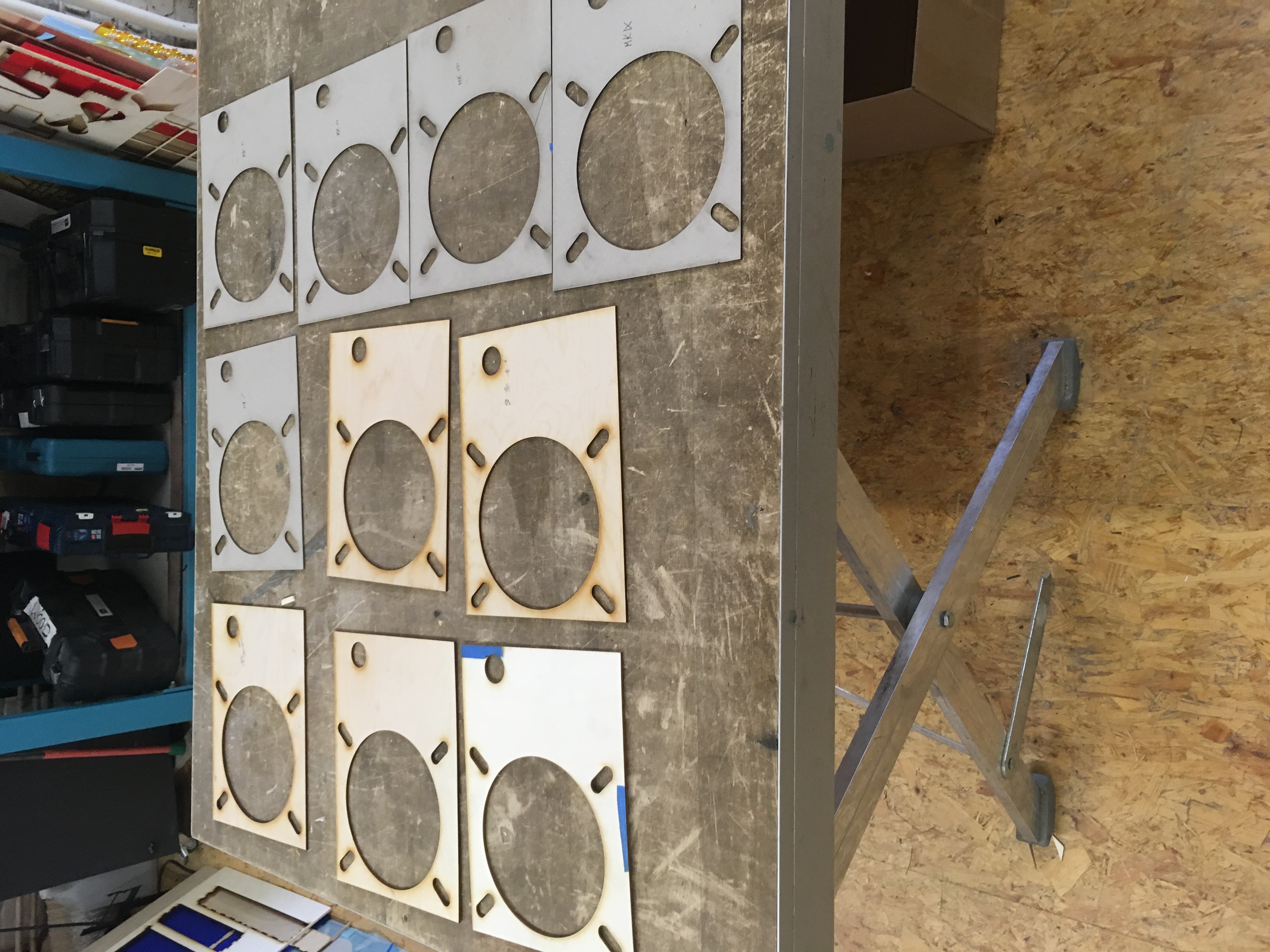
these cores, that i was designing, where 3 mm thick prints that took 30 minutes max.
so it was interesting to go back and forth between the drawing in fusion and the prints ,
the endgoal being to have one that passed nice and snuggly trough the coils.
there were 12 iterations with the 11th being the perfect one.
it went from a circle core to a polygon
but the right size and form of the spurs was the biggest challenge.
there is reality
measuring the reality
and the printed reality
i measured and measured again
but what was printed was not the same.
since i knew the lasercutter from the task before the residency,
3D printing was for me the most important thing to understand and master. so i went for it!
between what you measure
and what is printed
you have to take in account a tolerance
filament sets itself, it gets slightly “fatter” then what you have drawn in the software, so take it in account.
So: Learn how Measuring, Drawing and printing are related toward each-other and experiment with that!
3 .the rims and things
after i figured out the basics of the printers, i wanted to test them to their accuracy.
one of my installations /scenography’s is a Camera Obscura in which i use an iris to bring focus to the images.
an iris is a smooth mechanic device with fine blades, ideal to test the accuracy. the model was found on thingeverse.
i started off on the Delta printer with this new experiment, it has the smaller nozzle (0.1) then the Ultimaker 2+(0.6)
the Ultimaker 2 GO has also a 0.1 nozzle but i left it out of the equation for now.
this model has a lot of smal and thin pieces and thats not the same as straight forward 3 mm star shaped thing as before.
also i was trying to print several parts at once.
the first try went wrong because the printed part seemed to have been moving. it didn’t stick to the build bed and the next layers were not straight on top of the first, getting a wonky result.
so i tried to use a brim around the parts, but that was too much on these small and thin parts, although they didn’t move anymore.
the solution here was glue or hairspray.
don’t use to much glue though.. it really sticks the piece to the bed… the problem of the hairspray is the cloud of gas and smell
but it was easier to use… truth said, i never dialled my use of glue exactly right…
new problems arised on the Delta:
when halfway trough printing stuff got crooked and spaghetti tendencies started to appear.
it took me a while to figure out what it was.
i changed filament, also something i set up to do in this experiments just to learn how to do it.
and it was told to me that for the delta i could leve the filament spool on the bar and feed it directly and that i didn’t had to take of the spool off the bar and place it in the filament place on top of the printer.
it seems that the delta needs a smooth feed if filament, hence the bearings on top if the printer where the filament should go.
the feed off of the filament-spool-storage-bar wasn’t even enough and the filament actually pulled back.
my first solution to this was: pul on the filament so enough is off the spool, dangling above the printer to make the print.
but i learned that that wasn’t a good idea… when you take off too much, the spaghetti starts there and the chance is that the filament tangles itself , creates a knot and even bigger problems occur.
just place the filament you use where it should be, you will safe yourself a lot of hustle.
meanwhile, because of cours the printer was the problem and not my decisions ,
i switched on the Ultimaker 2GO to see how he compared towards the Delta.
seemed he was even worse… even the smalles attempt there failed because it didn’t feed enough…i could have switched off again, but since i was to curious i started to investigate…
after playing around with the tension on the filament-feed-contraption, because it was obvious that thing ate into the filament in stead of moving it forth, it went fine for a small test print, but then it went south again.
after a thorough examination, the screws that needed to hold the filament-feed-contraption in place, seemed to be loosend up.
after tightening them and calibrating the build bed (i used the instructions of the machine, which are a bit fiddly but not that bad)
the 2GO was actually a very good and reliable machine!
in the meanwhile i printed all the parts of the first iris on the Delta in standard settings.it was ok, but not smooth as it should be. the nature of 3D print gives you lines and a relief of cours that gives friction.
the next step i took was printing certain parts on all 3 the printers to compare. yes i included now also the Ultimaker 2+
and actually, it had a smoother finish. in retrospect that isn’t that crazy:thicker print lines means less lines, which means a more even surface. it is also on this point i started to play with the settings in Cura and see what they actually mean.
much further then this i didn’t go. this is all ready a deep dive in 3D printing and the iris experiment was hollowed out.
i made a second version (printed on the Ultimaker 2+). Which is a bit smoother but has the same problems as the first one.
3D printing isn’t really the way to construct an iris i think. i could have done a test with PET or ABS in stead of PLA, which would have been more ridged for sure but still not as smooth as it should. 3D printed iris’s are decorative, but not really practical.
4. that other machine and all in one.
the main reason i abandoned the iris was that i figured out what i wanted to figure out about 3D printing (besides the materials…)
and that i had came up with a project that could combine, lasercutting, 3D printing and CNC. so i had an excuse to learn the CNC !
In a performance of mine i use a record player that is modded with a 10 step acceleration up until “normal” speed.
so there is a knob, and with every click it goes faster and faster, the fastest is the normal speed the record needs.
last year i modded a cheap record player i head laying around. one of those with an USB port to archive your vinyl. It was very ugly and the speed control was build in temporary in a cardboard box. i wanted one unit, that was nice and neutral.
so i gutted the original one, salvaged what i needed to keep the record player working as it was intended and designed a new enclosure around it.
the enclosure was laser-cut. classic lasercut box with finger joints, but i tried to keep the finger-joints limited to the bare minimum.
i just don’t like the aesthetic of fingers everywhere so they are only on the upright corners.
the thing that challenged me here was trying to create a parametric box in Fusion 360. that u could re-use for any other box i ever have to make. and i will need that since i’m a guy that likes that things have there own boxes or crates.
for the record player there was no problem. proof of concept. but i need to tweak the parameters still a bit so it works for all future boxes!
then the stand-off’s was a 3D printing project. i salvaged the actual turning part of the record player and all the electronics
but they head to be placed at the correct hight, since i didn’t use the original enclosure. so little stands were printed to bring the turning table itself at the right hight and place the PCB’s on the right level so the inputs and outputs could stick out the side.
biggest quest was to create the aluminium top. the original had a thin aluminium cover and i wanted that in the new one too. aluminium means CNC.
but first i head to make sure the lay out of everything was exact. there is the turntable itself , and since it was a “pocket” turn table it had some pads that had to be in the right place, the hole where the arm came out and the hole for the speed selection-knob. all thise things had to be exact… and i spend quite some time making mock-ups on the laser in leftover acryl and cardboard and going back and fort to the drawing in fusion. only when i was 100% sure about it i went to the CNC.
i can not say i control the CNC… it’s not that much harder then the others, but at the same time it is… i guess it has to do with the refined brutality that it has. it’s impressive!
at the same time i have the feeling this is an old school CNC, from the time before the maker-movement. it’s not really user friendly… and too much tinkering. not that that is a problem, but it didn’t invite me, like the 3D printers or erven the laser did to experiment with it.
at the same time , why not learn the hard way on an “old school” CNC? but that would be something else and i should have a CNC only project.
5. project.
so, i did had just one project, that relied on the fablab tools, in mind when i started.
on the end of august/beginning of september i’ll have a new work in “Kunst & Zwalm” which is an art parcours in the Zwalm region, between Ghent and Oudenaarde.
in this new work, an installation i will use a misting installation and i found , while looking for the iris, 3D printing files for misting nozzles.
the idea was to create the misting installation myself, with 3D printed parts. but when i printed the first part i started to think into the physics that would apply and i quickly decided, after a a test with the printed nozzle that it would not be the myst that i was looking for.
it was more like some kind of rain.
the other part of this project is a LED spot very bright and very strong.
not a lot of fablab work on this at first sight, but i decided to build the lights myself.
no question that i will apply what i learned in the fablab to build the best lamp o can/.
probably i will nee a reflector, that can be 3D printed.
i will need a casing for the power supplies, that will be laser cut.
a bracket to mount the light on a tripod? i know how to start a CNC project!
and the best thing…
i know how it can be done
i know how to address the problems
and knowing how the machines work i minimalize problems that may accure while i need them.
in other words i can use the machines in a more precise way,
the fablab is now a tool.
Gallery


")


")


Info
FabLab residency
Date: June 2019 - July 2019
Last updated: July 2019