Use of Cura 15.4.6 (32 bit), 2.1.3 (64 bit) and 2.4.0
Version: 1.13 of may the 11th of 2017
In this article i refer to Cura 15.4.6 as C1 and Cura 2.1.3 as C2. C3 is Cura 2.4.0.
For C1 configure Cura according the used Ultimaker and for the Mandel90 as said at the end of the corresponding article.
For C2 chose the used Ultimaker and for the Mendel90 choose other printers than Prusa I3.
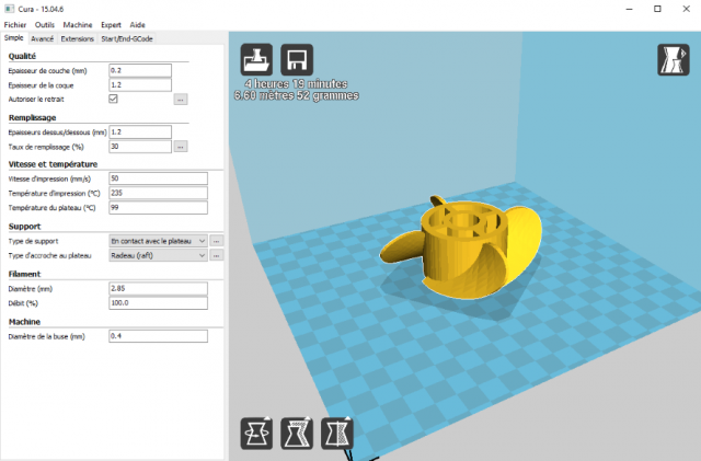
Bellow is a view of C1 with the first Tab (File-Fichier) opened and a part positionned on to the platerform.
The top right corner is the 3D part view Icon which allows to view the part in Solid or part of layers after creation of file ".gcode"
which is the feasible file (fichier exécutable) transfered into the machine for printing (réalisation).
At the bottom stay Part Rotations, Scales and Symetries Icons.
After the tenchage operation (slicing operation=décomposition of the model according the indicated thickness layer (selon
la couche indiquée) and the other parameters) you see above the Execution Paramerters: Time, Lenght
of filament, Weight.
At the bottom, you see in black the XYZ reference axis which must be at the left of the machine.
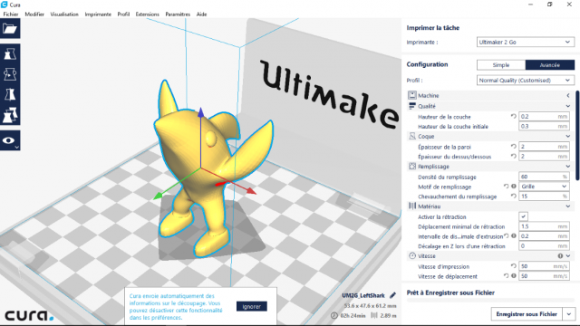
and here is C2 at the openning and loaded (chargé) with a part :
At the right you see - Type of used machine
- Type of Configuration: here Advanced
- Type of Quality: here normal customised (normale personalisée (modifiée)).
- The list of Parameters according those allowed (permis) with the Settings (Paramètres) Tab
above (dessus).
At the left you see, if the part is selected, 6 Icons (icônes): File opened (Part loaded), Part Dimensions, Part Rotations,
Symetries, Part Multiplier and 3D Part View ( in Solid or after by Layers after Trenchage ).
As soon as a part is loaded, Cura performs always the trenchage operation.
At the bottom, in the middle, you see the name of the part; below the dimensions, then the manufacturing time and
lenght of the filament used.
The ankles (chevilles) and the fins (nageoires) of the Shark (Requin) are thin. Thickness of skin=2mm (see further
(plus loin)) and Infill=60% allow to get solid ankles and fins.
NB: The blue message bellow in a white rectangular box is an optional help of C2.
Realisation and Parameters
1) At the opening of Cura choose the machine for your operation. In C1 and C2 it is with Machine Tab above.
You select with left button of the mouse.
2) Verify the parameters for that machine (Size of head displacement (taille du déplacement de la tête sur le plateau or
print bed) for X and Y, Max height in Z , Max temperature for the extruder, Max temperature for the print bed
( plateau chauffant) if any for ABS especially, diameters for the hot extruder buse (buse chaude d'extrusion) and for
the extruded filament (according (selon) the buse).
With C1: With Machine Tab you get Machine Settings (Réglage Machine).
With C2:- You can't change the X,Y,Z displacements of the head for the choosed machine.
- Choose a Profil with all the parameters for the part building ( See Paragraph 15 ).
3) Load (charger, open, ouvrir) a file type ".stl" (there are other types but ".stl" is the most used) which represents
your model with triangular faces.
4) Chose the face of the part that will be on to the plateform or at the bottom and put it.
Be sure that this face is well positionned on the print bed.
That position determines supports that will be constructed to maintain the overhangs ( parties en surplomb,
saillies). Always chose the position to minimize external and internal supports (see later).
Internal supports can be difficult to remove.
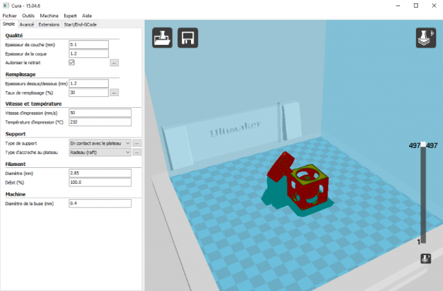
Here is an example (a ball inside and a hollow cube and fixed at the base) of position which gives better print than
the vertical position of the object. Supports can be more easily removed.
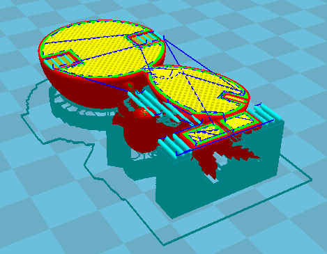
This picture shows the ghost (fantôme) of supports after the trenchage operation in layers View Mode.
Look at right: upper is the layers View Mode icon and bellow the vertical slider. Here we have 497 layers.
See bellow the parameters. Travel speed is 50mm/s.
Here are external supports which will support overhangs by the plateform (the row (rangée) bellow in
front of the next human face) and internal supports which will be constructed on faces of the part (other supports).
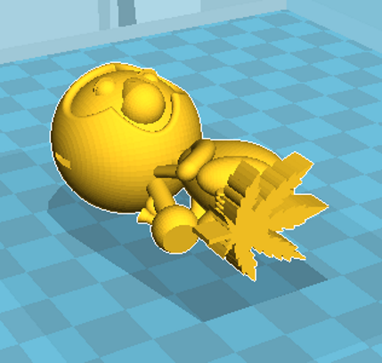
Here your have a musician monkey on to the plateform
and here you see the bottom layers before printing.
At the bottom you have the external supports on to the plateform and around the part the skirt.
In the upper layer you have internal supports (IS) for the ears. At the feet of the monkey, between
the jar and the stick you find also IS.
Supports can be difficult to remove especially internal supports integrated into the part. In general, hight density
supports is a problem to remove but they are necessary to get finally, after grinding (ponçage), smooth (douces)
and well-done (bien faites) faces.
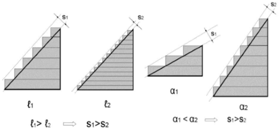
5) Chose the height (hauteur, épaisseur) of the layer according (selon) the level of details you want and to avoid
the stair effect (effet d'escalier trop visible). l is the thickness of a layer and alpha an angle.
Choose the thickness (épaisseur) of the skin (vertical shell, peau, coque, outline(contour)) and the height of the
upper and lower faces (horizontal shell) of the part to get smoothwell (bien faites) faces (to hide infills (cacher le
remplissage )).
Initial layer height is bigger than the normal layer height and allows to sick (coller) better on the print bed.
The Extrusion Multiplier or Extrusion Width increases or decreases the diameter of the deposited filament.
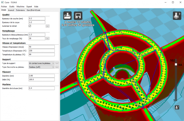
What is skin (peau)? Here is a cut inside of a pomp body with parts of wings (parties d'ailes) after trenchage.
It indicates layer number 142 on 162 totally.
Look at the internal cylinder : the wall comprises 2 skins (shells) and here in the middle the infill (if the thickness
of the wall is low there is no infill or you get a gap ).
The wall has two shells: the outer shell (peau extérieure) and the inner shell ( intérieure).
You see skins in red and uniform yellow at the 2 sides of the cylinder. Between them the Grid in yellow:
it is the Infill (Remplissage). Grid creates crosses at each layer inside the wall.
Look also at the beginning of the wings. You see that the two skins (on each side) are well connected: tickness
parameter of the skin is appropriate.
Choose thickness of the skin according the diameter of the nozzle ( buse ).
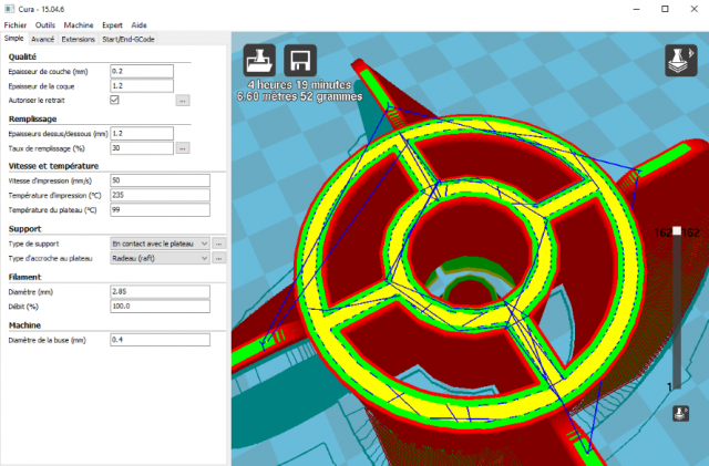
Here you see the top faces of this pomp under Cura 15.04.6 with the first Tab Simple opened on the left and the
parameters for layer, Skin and height of the upper and lower faces in Quality and Remplissage (Infill) titles (titres).
In C1 at the left you see these parameters.
In C2 they appear at the right. At the beginning you see only some parameters.
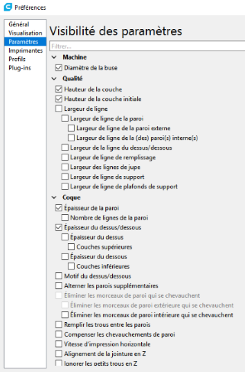
You must go to Settings(Paramètres)-Preferences-Parameters and click to a parameter to send
(envoyer) it to the right list of parameters.
Choose all those you want to appear (apparaître) at the right for configuration (modification).
NB : In blue you see the trajectories of the print head.
To get an appropriate view:
You see above a magnification of the pump. It is done by rotating the wheel of the mouse.
To displace the view of the plateform with the part you push on the wheel of the mouse and drag.
To rotate the same view you right clic and move the mouse.
6) Infill (Remplissage): Choose the Density Percentage and type of Infill.
Infill is the internal construction between skins to guarantee the solidity of the part.
The raster deposition ( trame du dépôt) is the way material is deposited according one axis
during the manufacturing of the slice. It is specified as an angle.
It can be a longitudinal raster at 0° ( line next line ) or concentric, perpendicular, at 45° or changing the
orientation from 90° every layer ( +45° and -45° ).
You have the Infill Overlap rate (taux de chevauchement in %) allows a better adhesion between Infill and Shell.
The Skin or Outline Overlap allows a better adhesion with the infill but also in the top and bottom layers.
In C2 you can choose the type of infill: Grid, Triangle, Concentric, Lines and Zig-zag.
Grid (Cross), triangle, Concentric : At every layer is a deposit on the preceding layer.
Lines and Zig-zag: the printer alternates directions from 90 degrees every layer.
It makes straight lines not parallel ( it seems to be if density is high).
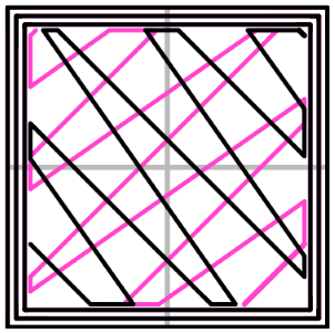
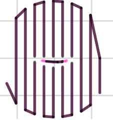
Here the lines pattern: line in dark for one layer; in blue for the previous.
You can choose the infill overlap ou Outline overlap ( recouvrement du remplissage ou
recouvrement avec la peau ) to allow a good adhesion between infill with the skin.
You can't choose the couple of directions for the infills: ex : 0° and 90°; 45° and -45°.
In C1 it is always Grid with directions of deposition oriented at 45°/-45° with the front.
Grid is proved to offer in general good strengths.
You can find also these patterns: Honeycomb, Rectilinear ( parallel spaced lines ) with other Slicers:
Repetier, Simplify 3D, etc...
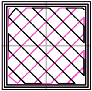
Here you have the rectilinear pattern (one layer in dark and the previous in blue) oriented at
45°/-45° with the front.
7) Speeds: Printing speed, Travel speed, first layer speed.
If you want a fine positionning reduce the travel speed.
If you have an inclined face, reduce also the printing speed (this allows also a denser deposit strengthened
by an appropriate printing overlap).
In C1 Printing Speed is in the Simple Tab; Travel Speed stay in the Advanced Tab-Speed and First Layer
Speed also in Advanced Tab-Quality.
In C2 All speeds are showed under Speed at the right.
Bellow is an example of a row part with faces sloping (inclinées) from 30° and printed with:
Print Speed=40mm/s and Travel Speed= 75mm/s. It avoids litte holes in the walls.
NB: Dimensions of tilted branches (montants inclinés)=3mm X 2,5mm.
Layer thicknes=0,2 mm; Skin thickness=2,4 mm; Bottom and Upper faces thickness=2,4mm
8) Temperatures for the Extrusion of Plastic : 210°C for PLA; 235°C for ABS.
for Print Bed: 99°C for ABS.
With C1 it is in Simple Tab
With C2 it is on the right : With the Ultimaker 2 Go it doesn't appear because it is fixed.
9) Activate Retraction if it must be it is in Simple Tab.
In C1 in Advanced Tab: here are different parameters: Retraction Speed, Max retraction distance.
Combing ( tourner autour ) is the fact for the head not to travel if possible above open faces then it is not
neccessary to retract = Avoid crossing outline for travel movement if possible.
With Expert Configuration Tab you can configure :
- Minimal Distance to allow a Rétraction to minimize number of retraction on shot distance: set at 1.5 mm
- "All": activates Combing for every type of face.
- Minimal Extrusion required before to execute a retraction to minimize number of retraction: set at 0.02 mm
In C2 it must be choosed in Parameters-Preferences-Parameters-Material to be displayed at the right.
According the choosed machine, some parameters are not allowed to be change then not to be view at
the right.
10) Activate Fan (ventilateur) to cool the deposited filament ( not too much ).
Don't cool first deposited layers to maintain adhesion with the plateform.
There is also a minimum time per layer to assume a good cooling. If the print of a layer is in advance it waits.
With C1 it is in Advanced Tab-Refroidissement.
In Expert Configuration Tab you find :
Minimal Speed for Cooling in %: normally the fan runs at the minimum speed.
Maximal Speed for Cooling in %: if the printer slows down the speed increases.
With C2 it is at the right indicated ( if it is permitted and choosed ) Ex: Maximal Speed for fan (ventilateur).
11) There are 2 types of sticking (collage) on to the plateform: Brim (bordure comme d'un chapeau) and Raft (Radeau)
Brim prints 1, 2 layers (Cura only 1) of curves (courbes) out of the base of the part on the plateform
like the brim of a hat. If the part is a vertical tube for example it prints brim inside also.
Used with PLA mostly.
Brims are often used to stabilize small parts or “islands” (isolated sections of a model, such as 4
legs (jambes) of a table) because brims help these delicate areas stay connected to the print bed.
NB: it is adviced not to print isolated sections of a model because elements can move a little.
In C1 you specify the number of lines in Experte Configuration.
In C2 you specify the width of the brim and the number of lines (courbes) on the right.
Raft is a horizontal latticework (trailli) of filament that is constructed underneath (sous) your part. Rafts are
primarily used with ABS to help with bed adhesion because this material curls like a banana (borders
curls upwards). Rafts are also used to help stabilize models with small footprints or to create a strong foun-
dation on which to build your part.
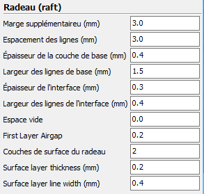
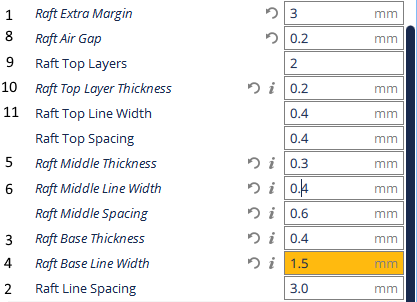
Here are the Raft parameters with C1 Expert Configuration which satisfy.
Raft consists of 3 different depositions: Base layers in contact with plateform, Interface layer (Intermediary
layer) and Surface (Upper layers) in contact (almost(presque) because it exists a hollow (vide) space (espace)
of 0.2mm) with part. The upper layer must be continuous (full covered).
1 Extra deposition out of base of part and space used for supports like a brim of a hat
(Marge Supplémentaire out of part)= 3.0 mm.
2 Base layer: space between lines (Espacement des lignes à la base)=3.0 mm
3 Base layer: thickness (hauteur) of lines (Epaisseur de la couche de base)=0.4 mm
4 Base layer: width of lines (Largeur de la couche de base)=1.5mm
5 Interface: thickness (Epaisseur)=0.3mm
6 Interface: width of lines (Largeur des lignes)=0.4mm
7 Hollow space (Espace vide): a supplementary thickness to the First layer Air Gap=0.0.
(see next line).
8 First layer Air Gap between last raft layer and 1st layer of the part allows to remove the part
(Disance entre dernière couche du Raft et première couche de la pièce)=0.2mm.
9 Surface:Upper layers: number (nombre de Couches de surface du radeau)=2.
10 Surface layer : thickness=0.2mm.
11 Surface layer : width of line=0.4mm
And here are the parameters for C2 according those of C1: The numbers correspond with the
parameters for C1 above. A tested modified version is given later.
You can specify the speed to print the base and its fan speed for the Raft.
12) Skirt : are layers (Cura only 1) of curves deposited outside the part to initiate the properly deposition of
extruded filament.
Always use that if you don't use Brim or Raft.
In Cura 1 and 2 It asks The Number of Curves, Distance from the Part, Minimal lenght for the Skirt.
13) Supports: 2 types : External and Internal
They are use to allow the construction of overhangs (surplombs, portes-à-faux, saillies). The external supports
are constructed from the plateform whereas external supports are constructed from a face of the part because
it is impossible to maintain from the plateform.
Choose : Supports On to the plateform (external) and Overall (Partout) supports which implies (implique)
external and internal supports. You can also choose NO support.
Supports can be: narrow Lines without alterning direction from 45° every layer, Zig-zag, Grid,
Concentric.
You find here the lines type:
With C1 you configure in Simple Tab (only ) and C2 in the right list of parameters.
You have to specify more parameters : Minimal Angle with no support, Density of supports,
Type of Supports ( Lines or Grid ), Minimal distance from the part horizontally and vertically.
Distance with the part in X and Y ( 0.5; 0.3 ), Distance from the part according Z ( 0.15 mm ).
In C2 you can specify the horizontal speed for supports if it is implemented by Parameters.
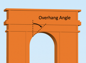
What is the Minimal Angle for support? : See the image below
It is the Minimal Angle with no support. Then if it is 20° all slopes (inclinaisons, pentes, parties horizontales)
between 90° from the vertical to 20°1' will get supports.
Types of Supports :
In C1 They are constructed in narrow Lines according Y or Grid.
In C2 you can choose more types of support and use base dimensionned towers (Pillars)
and specify the angle of the roof (toit).
14) Particularities of C1
-You can load a profile ( Parameters ) from the saved ".gcode" for a part. It is a facility!
-In Expert Configuration you find Filling (Remplissage) and Repair (Reparation).
Bellow are the Supplementary Options for filling (Remplissage) : check 2 upper lines.
You see also the overlap ( chevauchement) between infill and inner walls here = 15%.
It is the normal value to weld infill and skin.
Here is the box for Repair: option A always checked.
If you have deposited a vase with the bottom on to the plateform, if you look at the
bottom with the mouse after trenchage, you'll seen no bottom but it will print the bottom
of the vase.
If your part is a cylinder vertically set on to the plateform, if you don't check "Keep opened
faces" or ("Conserver les faces ouvertes") it will create a bottom.
15) Particularities of C2:
-The trenchage operation (slicing) appears at the right bottom.
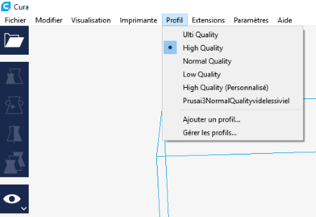
-Immediately after the choose of a printer, choose the Profil. There are different Profils as seen bellow.
You can Change parameters at the right, Add parameters to the right with Settings (Paramètres)
which is the sixth Tab above.
Here is a view of the first parameters which can be included in the right list.
Then your Profil become a Personalised Profile.
With Management (Gestion) of Profils, you can rename the used profil and save it.
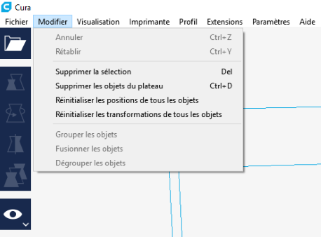
-A part of the possibilities in Fichier Tab of Cura 15.04.6 are set in the Modify Tab.
You see at the first position in the ribbon(ruban): Annuler last action.
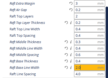
-The Raft Parameters must be modify from those seen above (paragraph 11).
The purposes are to evoid the banana effect specially in the corners and to remove easily the part.
Here they are:
16) Visualisation of how will be your printed part before realisation:
For C1:
After the trenchage operation (which appears by the filling of a bar above under the 2 upper icons),
click on the right upper icon, 5 icons appears down, click on the last one, the construction for the
visualisation appears at the bottom, wait the end (if you don't wait the visualisation will be wrong) the
end and look inside at all the elements. (ex: Shark: feet, ankles, legs, belly(ventre), fins, head) of your
part to see if walls and infills are correct everywhere.
With some parameters for the vertical cylinders of the pomp there are gaps in the walls of the cylinders
then lack of solidity. Then save the ".gcode" with the parameters. All parameters constitutes the profil(e)
for the building of a part.
For C2:
After the trenchage operation you can View the layers (couches) of the manufacturing.
With View (sixth icon on the left) you have 3 possibilities with the arrow to the bottom:
Solid mode (view of the part in 3D on to the plateform), X-Ray mode and Layers view.
Click on layers view: the construction for visualisation of how the part will be with supports
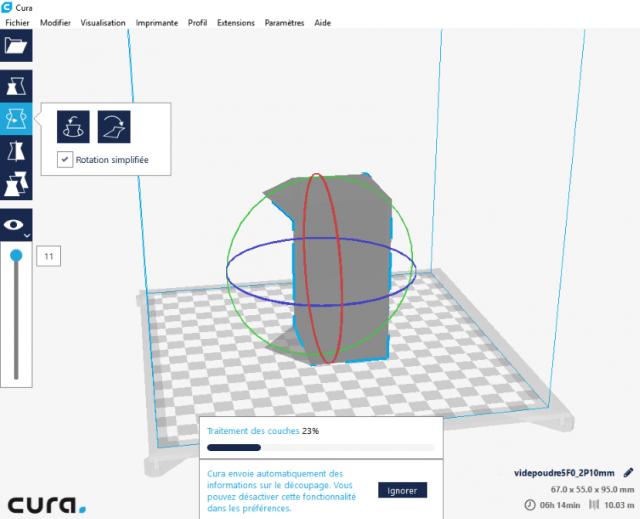
begins. It can take time! Cura constructs the visualisation of layers at the center bottom.
Wait for the end and after you can examine the realisation of the layers and supports with the slider
under the eye icon which indicates the top layer viewed.
What is interesting: to look at layer by layer set the mouse in the layer number rectangle.
With the Key "Down Arrow" you can decrease from 1 the layer viewed. With the Key
"Up Arrow" you move upper.
The entire part can be viewed over the bottom layers. It is because the part is selected.
Click outside of the part to see the layers.
Then save the ".gcode".
NB: the indication of 11 near the slider is no valid here because the visualisation is in construction.
17) Cura 2.4.0 comes from C2. It is the same environment but the second icon on the left is added.
It is to displace the part in the space.
The last icon, the "eye" is to switch from Part Solid 3D View , X-Ray View and Layers View very useful.
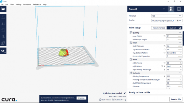
Here is a view how C3 looks like :
You see on the right from above to bottom :
Type of printer chosen, the white arrow to switch from it, the hour-glass ( sablier ) permits to edit the parameters
and the squares icon is for monitoring the state of the printing if you PC is connected to the printer.
Material used; You can change with the black arrow at the right.
Profile used . A Profile is all the parameters used to do a job. You can save it to rename, call it again for an
other manufacturing.
If you change a parameter of the profile you get a star. The possibility to chose an other profile is given
with the black arrow.
There are predetermined profiles ( protected ) that you use to create a custom ( personnalisé ) profile
and name it so that you can use a next time.
Print Setup : The list of parameters for this Profile.
Recommended or Custom. With Custom you can change the value of the parameters of the following list;
you can also add more parameters or change some.
At the bottom middle you get the dimensions of the part and after slicing ( tranchage ) time and length
of filament needed to manufacture it.
At the bottom right you have the possibility to save you "gcode" file which is the file used by the printer.
Bellow the list of parameters, the program indicates if you can save the "gcode" file after the slicing operation.
Wait a while if not. It takes a time ( indicated by a progressive bar bellow the part screen ) if you want to
see the layers after slicing .
If you change a parameter in the list of the profile, the program begins immediately to slice again.
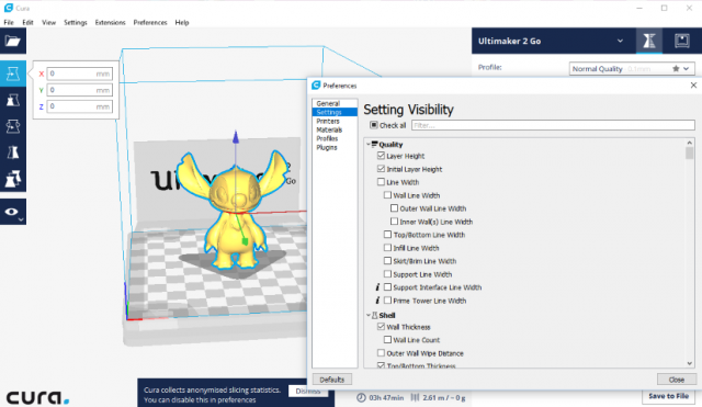
If you want to add some parameters you click on Preferences above ( 6th in the Menu ) , then Configure Cura
and Settings. You get a list of all parameters you can check ( cocher ) to insert them to the parameters
of your profile at the right.
NB : This specimen must be printed horizontally.
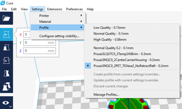
To get access to profiles you click on Settings ( the 4th menu ) then Profiles.
A list with the profiles appears followed with commands: Create, Update profiles, Discard changes.
If allowed these commands are black. You find the same commands if you click on the arrow in Profiles
above in Print Setup on the left.
The last is Manage Profiles.
The used profile is indicted with a black point.
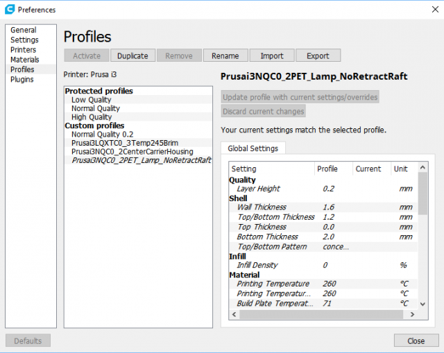
Manage Profiles looks like this :
6 possibilities in the Menu : Activate, Duplicate, Remove, Rename, Import, Export.
Bellow the second window shows the profiles.
Above the third window you have the name of the used profile.
If you have made change in parameters you are allowed to Update ( this ) profile with current settings/overrides
( put in Print Settings on the left ) or Discard current changes.
Follow the list of parameters. If one change has been made the corresponding parameter value is crossed out
( barrée ) and the actual value is given.
According to the situation you can Rename a profile to better reflect its purpose, Export ( save ) it by giving an other
name ( for no confusion in you import it later ) or Remove.
18) Met Terminology (Terminologie rencontrée) and Parameters :
Bead Width or Line Width ( Cordon de soudure ): it is the width of the plastic line (curve) deposited.
It is given as the nozzel width or sometimes set at 1.
So the second line is deposited to touch the first line to get adhesion. If you want more adhesion decrease it
a little. If it is increased you get a lateral air gap.
Here i have printed with C2 and a tip of 0,4 mm a wall width of 5,2 mm with layers of 0,2 mm,
with perimeter of 4 lines inside and outside and grid infill and set the Line Width to 0,3 mm.
See the result : lateral lines copenetrate.
and here see the result with Line Width set to 0,5 mm : The perimeters increase but lines don't touch
very well and infill area decreases.
Conclusion : for a tip of 0, 4 mm it is better to set the Line Width to 0,35 mm
Oozing (suintement) and Stringing (pulling a hot filament when head is moving over open space - tirer un
fil lorsque la tête se déplace sur un espace ouvert). We obtain like hairs between components of the part.
For this reason we have two parameters: Retraction Distance and Retraction Speed seen above.
You have also: - Retraction minimum travel : it retracts for a longer travel as mentioned.
It prevents from doing retraction when it needs to move a small amount.
- Retraction minimum extrusion distance: to not retract for very small deposition.
Too much especially for thin layers and is problematic for the flow of the filament.
You can find more over "Extra Restart Distance": At the beginning of a deposition you can have too much
deposition.
So use this parameter to enter a little negative value to decrease the deposition.
Coasting or deposition by inertia : at the end of a deposition you can get too much deposition. Use this
parameter to enter a positive value which retracts before the end.
You find also: "Only retract when crossing open spaces".
Wipe nozzle (nettoyer buse ). Retraction in case of head stops indicated in mm. It Evoids deposition if head stops.
A bridge is where plastic fills a gap in space between two plastic areas.
Shell is specified with its thickness and Perimeters is specified in number of lines.
Most Slicers don't speak in term of shell but perimeters. For exemple a cube.
You can find cube printed with 2 perimeters or 2 deposition lines side by side at the outwards;
it is 2 X Nd ( nozzle's diameter ) in mm. You can also find cube with 3 or 4 perimeters.
The number of lines has an impact on the strenght as the infill.
Now the 64 bit version coming from Cura 2.1.3 is Cura 2.7.0
I expect that this will help you.
Good work.
Info
Difficulty: ●●●●○
Last updated: September 2017
