Inkscape and the Lasercutter
Inkscape is a popular Open Source vector graphics editor which can be used with the Cyborg laser cutter at iMAL.
SmartCarve, the laser cutter software operating the Cyborg, is using the DXF file format for importing vector graphics and Inkscape allows us to easily export our SVG projects in DXF format.
This article illustrates some "do and don't" when using Inkscape in combination with SmartCarve at iMAL.
General remarks
Inkscape Version
Ensure you are using the latest version for your operating system (0.48.4 at the time of this writing - March 2013).
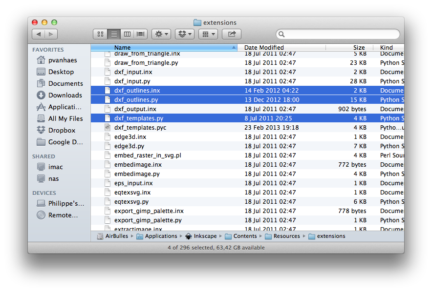
Note for the Mac users: the latest bundle available for Mac OS X is still 0.48.2. Although this version is working very well, the DXF export filter is a bit outdated. After installing 0.48.2, download the 0.48.4 Source Tarball and copy the following 4 files from the source tree to your Application package in the Contents/Resources/extensions directory:
- dxf_outlines.py
- dxf_outlines.inx
- dxf_templates.py
- simpletransform.py
Units
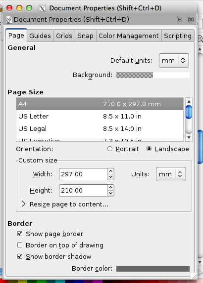
By default SmartCarve expects units to be millimeters. Ensure your drawing units in Inkscape are set to millimeters as well!
(Actually it will probably work with whatever unit you choose, but if the size of your final project matters and you choose to work e.g. in pixels, it will be less obvious to see how big your project will be in reality)
Stroke width
Stroke width does not matter as such, the laser cutter will always cut in the center of the line.
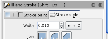
Again if the exact size is important to you, use a very small stroke width (e.g. 0.01 mm) as the measurements given by Inkscape are always including stroke!
In some cases you may want to set the stroke width to the kerf (see below)
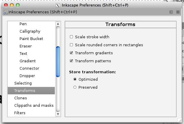
Note that by default Inkscape will scale the stroke width when you scale the objects. Typically we do not want to do that and this can be changed in the Inkscape Preferences, Transforms tab
Kerf
The kerf is the width of the groove made by the laser while cutting. It varies with the material used and the depth of the cut (about 0.2 mm).
If you need an exact fit between 2 objects, you need to take in account the kerf.
As said above, you can visualize the kerf by setting the kerf value as stroke width.

A 4x4cm piece of 3mm MDF cut at the FabLab measures 39.8mm, we have here a 0.2mm kerf.
Exporting to SmartCarve
The examples hereunder are based on the following Inkscape project:
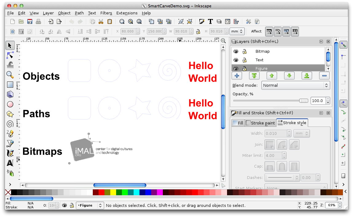
The first row contains Objects, the second row the same objects converted to Paths and the third row a Bitmap.
The labels, figures, texts and bitmap are in 4 different layers and also 4 different colors.
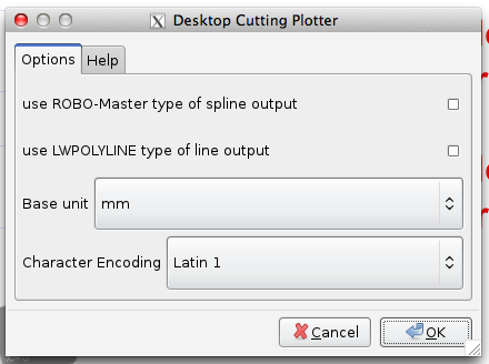
Using the DXF export module
The simplest way to generate a DXF file from Inkscape is to use the DXF export module (I guess you already figured that out!).
Before exporting to DXF, you need to make sure that:
- All Objects are converted to Paths (Menu Path - Object to Path)
- Avoid using 'Groups' which may confuse SmartCarve
- Uncheck both 'use' options in the DXF export module (LWPOLYLINE will not work as expected),
- Base unit is set to millimeters
Note that Inkscape Layers can be converted to SmartCarve layers at import time, so keep that in mind when you design your project: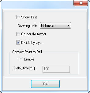
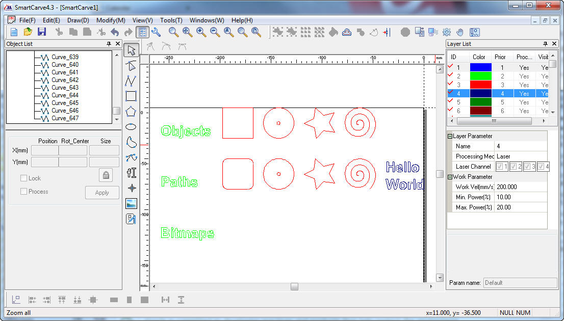
Result in SmartCarve is as expected:
- The first row does not render properly because these are objects (the square does not have rounded corners and the text is missing)
- Second row is correct -- this is what we need!
- Layer grouping is respected based on the Inkscape layers
Caveat: while this approach is simple and works very well, the paths will be exported in several pieces, which means you will not be able to fill them in SmartCarve.
This is problematic if you want to engrave/etch as this requires closed curves.

The above figure shows that the square has multiple curve segments.
Using EPS export
An alternative way of generating a DXF file from your Inkscape project is to export as Encapsulated Postscript (EPS) first and then convert the EPS file to DXF using pstoedit, a free software tool.
The main advantage of this process is that all closed Paths will remain closed when imported to SmartCarve, so it is a good alternative when you need to engrave.
Pstoedit is a command line tool widely available:
- On Windows 32/64 bits: download from the pstoedit website.
- On Linux: it is included in all popular distributions, use your preferred package manager.
- On Mac OS X: use your favorite package manager, pstoedit is in MacPorts, HomeBrew, Fink, ...
When using the EPS export way, you don't have to care about Object to Path conversion, it just all works!
So the steps are:
- In Inkscape, save as Encapsulated Postscript with the following options:

- From the command line, do the final conversion:
pstoedit -f "dxf: -mm" MyProject.eps MyProject.dxf

That's it, you are ready to import in SmartCarve, and this time, complete paths will be preserved!
Objects are now rendered correctly as well:
Path are closed and can be filled:
Note that Inkscape layer information is lost in this process, but pstoedit is able to map colors to layers in the DXF file. If you assign a different color to each layer in Inkscape (which I always do), you will find your layers back in SmartCarve (see above). You need to add the '-ctl' option in pstoedit to enable this feature:
pstoedit -f "dxf: -mm -ctl" MyProject.eps MyProject.dxf
Caveat: when dealing with very small objects (2-3 mm), the conversion to line segments in pstoedit is not perfect -- see teh following example with a 3mm diameter circle:
If you think it is important for your project, an easy way to improve the resolution is to scale up your project in pstoedit and scale it down afterwards in SmartCarve (factor 10 scaling is good enough):
pstoedit -xcale 10 -yscale 10 -f "dxf: -mm -ctl" MyProject.eps MyProject.dxf
The same circle using this technique:
Alternatively, you can scale by a factor 1000 in pstoedit and import in microns in SmartCarve, but the DXF file will be rather large:
Working with bitmaps
None of the methods described above are showing the bitmap in SmartCarve. This is the normal behavior as the DXF file will only carry over your vector graphics.
If you want to do bitmap engraving in the same project, you will need to export the bitmap separately.
The following steps will ensure that your bitmaps will be positioned at the right place when imported into SmartCarve:
- Ensure all your relevant layers are visible (both bitmaps and vector graphics)
- Select the bitmap(s) to export
- In the Export Bitmap menu

- Select 'Drawing' as Export area (this will ensure the bitmap is aligned with the project in SmartCarve)
- Enter 120 dpi in teh Vitmap Size region (Size in pixels will be set accordingly)
- Check 'Hide all except selected' option (only your selected bitmap(s) will be exported)

Inkscape will export the bitmap as a PNG file, which is not supported by SmartCarve; use your preferred editor to convert it in BMP, GIF, ...

Note that
- SmartCarve will typically import your bitmap in hte first layer, you probably want to move it afterwards
- You have to raise the priority of the bitmap layer to have it 'under' the other layers
And here is the result!
Inkscape extensions
Some interesting Inkscape extensions...
Tabbed Box Maker
Boxes are popular in laser cutting projects. The Tabbed Box Maker extension allows you to create box templates directly in Inkscape and is quite comprehensive.

Hershey Text
Engraving text is often a problem: fonts converted to paths (outline fonts) are not always rendering nice, and converting them to bitmap is rather slow to engrave.
Hershey fonts are vector typefaces specially suited for engraving. Hershey Text is an Inkscape extention which brings your Hershey fonts in Inkscape!

Enjoy!
Info
Difficulty: ●○○○○
Last updated: March 2013