Form 1 + : First Print
Vers. 1.9 of Oct the 4th of 2017
Software version : Preform 2.10.3
fablab members:
1. Before the first print, all new users of the Form1+ must take at least one hour to read the help center tutorials from formlabs
These tutorials are basic informations that you must know (devez connaitre) before (avant) you work with the machine.
For the operation of the machine, take special attention reading these sections:
Checking the resin tank / filling the resin tank / printer care / Resin care / Resin tank care, Cleaning after a failed print /
2 . And Each fablab member needs to have his own Tank.
Members can buy (acheter) tanks (bac de construction) directly from formlabs (constructeur de la machine) or they can buy it at the lab for 65€.
This must encourage members to take care (de prendre soin) of their tank and to follow (suivre) all the steps needed to operate the machine properly.
Members can also buy their own resine (resin at fablab costs 0,60e / ml)
3. To prevent failed prints
Shake the resin bottle before usage.
We advice (conseillons) members to clean (nettoyer) properly their tank (bac) according "Form1+:
Take care of your tank" on the Howto. It is important to clean the external bottom of your tank before
printing with a glass ( spectacles) cleaning Wipe.
Before using resin in your tank, with a paddle, slip ( glisser ) carefully on to the silicone layer the resin
from the back to the front of the tank to take off ( décoller ) particules of resin glued on the back of the tank.
It is very important to be abe to estimate the quality of the resin in the tank before usage.
After a bad realisation, Pieces or Particules of irradiated resin stay inside, at the bottom (fond)
and can hinder (cacher) rays (rayons) of the laser beam (faisceau laser).
Try to identify these particules. It is easier with clear Resin!
Don't hesitate to filter the tank in a bottle (bouteille) for reused (réutilisée) resin of the same type
and number.
Identify the filter used with that resin and don't waste it.
There are 5 types of basic resins. Don't mix resins. If you suspect irradiated particles resin in the tank, use
the appropriate identified bottle to filter that resin.
For a type of resin there are different qualities. Exemple: clear resin exists with 3 formulas: 1, 2, 3.
Ask Julien Maire (J.M.) if you are not able to evaluate the quality of a resin.
Fix the tank lateraly by little pieces of wood or plastic . In front and at the rear of the tank, laterally, you insert (insérez) them between the tank and the rails.
Ask J.M. or Jean Dacos.
Put a thin (fin) film of resin (résine) on the plateform where your constructed part will be attached with a paddle.
Take a look (regardez) at the mirror inside the machine beneath (sous) the position of the tank. Use an air bomb first
to clean the mirror, then a wipe.
Be carefull ( Soyez prudent) with Preform.
1) It places very few (peu) supports to attach the part at the plateform. Don't foreget (n'oubliez pas) part is
constructed up side down.
Manually put many more orderly (organisés) supports to attach the part according to the weight and get
well-done (bien faits) sides (côtés).
2) Follow the supports put automatically ( according Density, Slope Density that you chose ) by Preform for
overhangs (porte à faux) for external and/or internal supports.
External supports maintain overhangs from the plateform. Internal supports maintain overhangs from
faces constructed of the part.
Take care also for the size of top point of supports ( Tiny for delicate piece portion ).
Generally it puts to few supports. Change the orientation, parameters or Add and Displace supports manually to
maintain overhangs, certainly where Preform indicates red zones .
3) If you put the part at the right on to the plateform with Preform, the part will be constructed at the left ( upside
down ) of the plateform. The left ( during the construction) is the better place for the part because the tank toggles
(bascule) clockwise between each irradiation and the flow (flux) of resin is lower at the left of the machine.
4) If you have a part with a vertical fine edge (wall) place it parallel to the front otherwise (autrement) it will be
tilted (incliné) by toggeling.
5) Put the part with the finest details at the right on to the plateform of Preform but if you print an inclined medium
size model, due to flat bottom, set the higher (and ticker) supports at the left with Preform because they will be
stronger against the flow during the tilting.
6) The tilting of the part in a vertical plane has an influence to the quality.
7) Flat surfaces ( >= 1 cm² ) with supports give better result with a part clockwise angle ( front view ) between
15 and 20 degree ( then tilted to the right on to the plateform of Preform).
After each layer, the printer processes a peeling ( un décollement ) of the last irradiated ( printed ) layer from the
silicone layer at the bottom of the tank by rotating it clockwise ( downwards ).
This process can damage the deposited layer when the tank is tilted.
For each layer, minimalize the irradiated zone to be peeled.
The tilting to the right of the tank during the manufacturing generates a flow of resin with lower impediment
(empêchement) and pressure on the manufactured part and supports during the peeling process if it is tilted to
the right on to the plateform at the positionning time with Preform.
Find here an example of orientation of a basket from the front vue :

Here are 2 images of a test model to see if holes of different sizes will be very well manufactured. In fact it is.
In each of 3 faces there are four holes with diameters of 9, 7, 5, 3 mm. It is done in clear resin number 2 and
irradiated with a layer of 0,1 mm.
Here you see almost the orientation of the part in Preform ( the face on the right is aligned with the right border in
Preform ). You see the tiny supports to the right under the bottom face.
On the front face are supports for the lateral face.

And here are the holes inside 1 face.

Here are 3 images of the main body of a liquid minivalve commanded by air depression.
It is also done with clear resine number 2 and irradiated with a layer of 0,1 mm.
This time for a better illumination for the photography the part is rotated almost 120° clockwise so the left face
is aligned with the right border in Preform.
I have put the 2 tiny outlets of this face of the minivalve to the right so that the supports don't touch them.
You see the tiny supports aligned with the lower flat bottom.

Here you find the upper face with lateraly the inlets for air and in the center a rectangular hole to insert the shuttle.
In this hole will be glued a part with the inlet of liquid. The upper face of the central hole is upwardly domed
( bombé vers le haut ) by manufacturing ( it is constructed up side down ) and by the curing after.

and here are the very well done internal channels.

8) Grey resin demands more power to irradiate than the clear resin.
9) Here are the minimum layer thickness you can use according the resin type. For Form1+ and Form2 indicated with V.

Contact formlabs support by email (support at formlabs dot com) sending an explanation + your stl and formlabs files. Their feedback is very important.
Send your failed print project to the formlabs community forum
Or Ask the fablab managers for advise.
Basics
Take extra care when you manipulate the resin, the resin tank and the printer.
Resin are valid 1 year according FormLabs. I thing it is for commercial purpose. In pratice i should say 2 years probably.
The printer is autonomous, your computer doesn't need to be connected during the printing process.
But you have to bring your own computer with Preform to scale, position, enter parameters for the process and upload the file into the printer.
The more precise you print, the more time it'll take. And keep in mind that 0.1 is still extremly precise.
Printing one model or many won't take much more time. To be time efficient, print several models if it is possible according the parameters.
Resin react to the UV light. Don't expose the resin to the light.
Some Software Printing Basic steps for Preform ( use Form1+, Form2 )
At the openning, the window looks as the image bellow with above in the Menu: Fichier (File), Modifier(Modify), Afficher(Show) and Aide.
At the left 5 tools on a dark vertical ribbon; in order from above :Dimensions, Automatique Preparation and Print ( not advisable ), Orientation, Supports Generation,
Position on to the plateform and Object Multiplier.
Bellow is an image of the printer access in orange.
At the right + and - icons are to show the image greater or smaller. Then in the center of the cross is for the view in 3D.
The 4 arrows around are to show from above, from right, and so one.
A window in the center ask you the type of machine, type of resin and layer thickness.
There are two tiny bars in white: on the right of the window with a dark little square slider (glissière) bellow
and one at the bottom.
Then push : commencer or begin.

By using Fichier Ouvrir(Open) load a ".stl" file which places the part on to the plateform. The name of the file appears before the name of the program above.
Here is the window of Fichier(File):

The first line: the icon with the magic wand and stars: impression en un clic ( print in one click ) : i think it is only for amazing ( épater ).
The software asks you if it can repair a model with some issues if any.
Left click on the part to select it if not ( bellow the fish ) , it must be blue.
Scale your model with Dimensions, the first icon on the left: the easiest is to change l'échelle ( the scale ) at the bottom
because it maintains the relationship between the 3 dimensions X,Y,Z.
To close the tool after, click on the icon.
The Counterclockwise Arrow at the right side of Echelle ( Scale ) is a back return to the previous situation.

To increase or decrease the scenery, rotate with the central wheel of the mouse.
To displace the scenery, push on the wheel of the mouse and drag.
To rotate the scenery, push on the right button of the mouse and displace.
Place precisely your model on the printing surface. It's best not to always print in the same area. Some area are deteriorated by the laser in the long run.
To do so, click on the fifth tool on your left in the black ribbon which is Agencement ( Arrangement ). You see the plateform from above with the part.
To move the part on the plateform, left click on the object if not selected (must be blue ), with the left key of the mouse drag to a new position.
With this tool you can also duplicate a part as indicated in Agencement ( Arrangement ).
Remember: part is constructed up side down so the fish below will be printed at the left.

To view the part in 3D again, click on the right key of the mouse and drag, the view of the stage with the object turns.
You can rotate the part. As you have seen, to manipulate a part it must be selected ( in blue ).
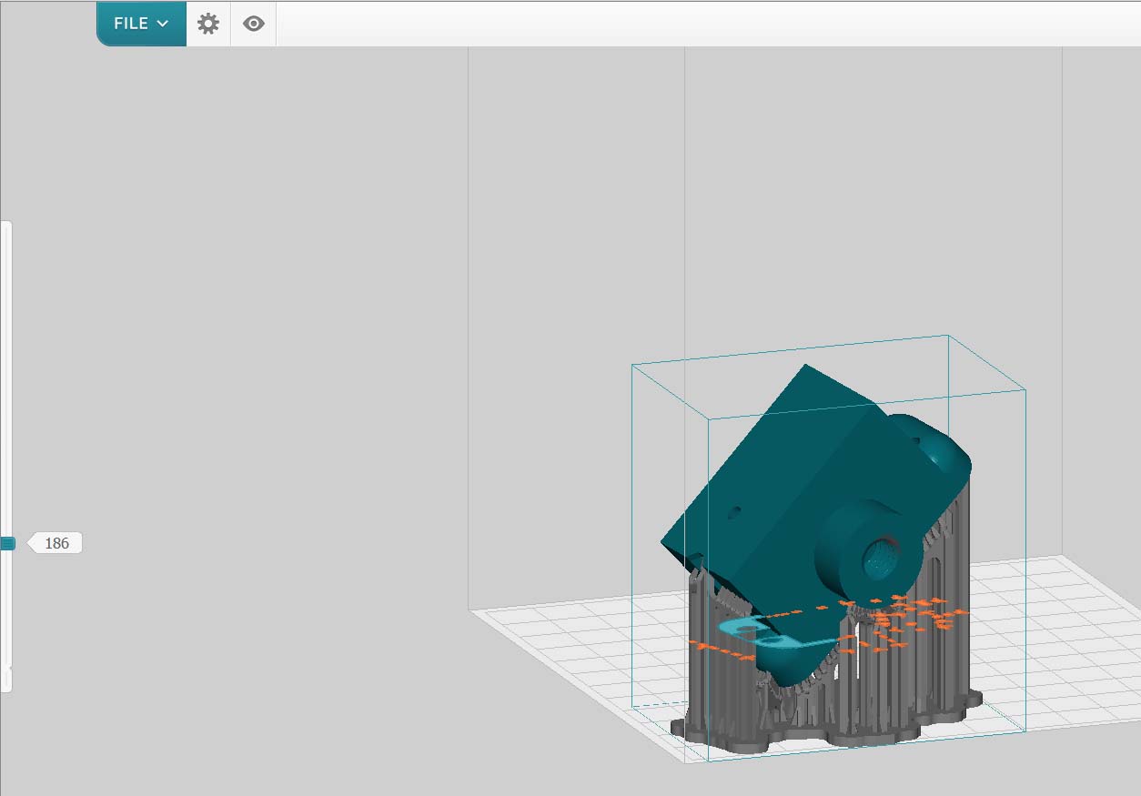
Click on Orientation. In the case below i have rotate with an angle of 8 degrees the part according X axis to move the head lower.
Bellow you can view the part from different positions. This model has no base.
The first string white on blue : Faire pivoter la sélection ( Rotate the part ) rotates automatically but the position
achieved is not neccessary the better.

With this tool you can also chose a face to put on to the plateform with Sélectionner la base ( Selection of base )
in a white rectangular box under different views.
On the image below ( a cap ), the upper face of the cap must be placed on to the plateform. As you click on
sélectionner, a red arrow appears, which will be placed on to the face that will be put on the back . Look at the image
bellow.

Result:

Don't print so because you know you must incline the part !
Generate Supports
Depending on your model you should change some parameters. Keep in mind that the supports are
here to support your model, it'll be hanging from the plateform.
If it's a heavy model, you'll need more strength so more supports. Left click on the icon with supports on the left to open the tool.
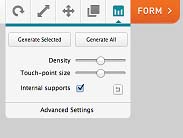
Under the bue commands, at the first openning Densité= 1.00 and Taille=0.60 mm.
For supports: Choose Densité( Density ) and Taille( Size ) of sommets ( Point Size ) which maintain the part.
Check Supports internes(Internal Supports) if it needs. Internal supports maintain overhangs from constructed faces of part.
Then click on Création automatique ( Automatique creation ): The soft indicates below the progression of the operation in the bar.

Above the lower bar you 'll see the informations for the realisation: Volume in ml, Number of layers, Printing time, First
parameters chosen at the opening of the soft.

Result for Densité=1.00 et Taille points=0.60 :

The soft generates a removing base on to the plateform at first.
If you chose Densité=1.3 et Taille points=0.80

NB: For my part i have put the support which is at the base of the eye of the fish a little lower.
These are not supports for Slope Density ( Densité pour les parties inclinées ) = 4.0.
Even with this Slope Density i have manually repositionned a lot of supports for better details
or better constuction.
Supports: Paramètres avancés ( Advanced parameters ) in a white rectangular box, under Suppots internes : Four parameters appear in the window.
Densité lors d'inclinaison ( Density of slope ) is the most important. It increases the supports density for slopes.
You will see Espacement entre supports ( Spaces between supports ) decreases as Density increases.
Under Density you see Epaisseur de la base ( thickness of the removing base ) and height from the base. It is not easy to remove short supports!

If your model have red areas that means that these areas will have some printing problems.
You should find a better position or change parameters. If it can't help the better is to go to
Mode manuel ( Manual Mode ) to delete, change or add supports. You see the part with pink points
where supports are located.
You can orient easily the part by pushing the right key of the mouse and dragging.
You must imagine the part will be printed with the head of the fish above and according to this
fact you place supports to horizontal planes and lateral slopes viewed from the back so that
irradiated resin can agglomerate and be supported.
Attention: face can be inclined according two plans X,Z and Y, Z in the space.
Before adding supports verify the Taille des points ( Point Size ). It must be the same as those
chosen for the automatic generation.
One can increase the size of PS on the right of the part on to the plateform in Preform to resit againt the flow
during the tilting.
If you have sharp borders, to get well done borders you must repositione supports alongside the borders.
To remove a support: left click on the pink point. To add, locate the mouse on a point on the part and left click.
Here is a view of manual repositioning supports:

When it is done, click Appliquer les nouveaux supports ( Apply new supports ).
Check the support contacts and layers with the black layer's viewing slide on the left of the screen.
With the slider at the bottom you see the whole part.
If you move it above, after a notch, you will see a layer and supports with the back of the part from the plateform.
Move the slider Up and Down to examine layers and supports.

Window of Preform : First row above with tabs after Fichier
Here are the interesting possibilities with the Modifier ( Modify ) Tab : according the concept, the two first lines can change.

Here are the options for Affichage (Show)

then you can create the file for the machine: file ".form" by Fichier Enregister sous and choose a location for use latter.
Printing: You have to check the resin before.
First check that there is enought resin. They are 2 marks on the resin tank for the maximum and minimum.
If you print a huge model, you'll be able to open the printer and refill the tank with resin later.
Before printing you have to gently move the resin with a scrapper ( not to push on the back to much ) for about 2 minutes.
Otherwise some resin is may be glued to the bottom silicon layer of the tank.
Check the aspect of the resin. No particules of previous print should stay. When all is right close the cap.
Is the power supply connected? If yes push the button in front : The display opens up.
When the initialisation is done, connect the USB cable of PC to the printer ( You 'll see the connection done by an usb
cable in the orange icon ) and then click the orange button Form.
Be patient. The machine file is transfered to the printer. You have to press once the printer's button to confirm.
The printing process begin as soon as the first layer is upload. When the uploading is finish you can disconnect
the USB cable.
The printing time shown on the printer is exact.
laser light can cause irreversible dammages in the eyes and skin. With spectacles you can look at the ray through
the protecting cap. Don't open the Cap.
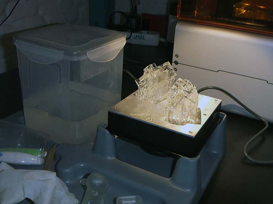
When the print is done, shut down the printer. You can now open the printer and remove the platform with the handle.
Place the platform on the finishing kit.
Remove your model with the scrapper.
Then place your model in the isopropyl alcohool which is inflammable.
Pay attention not to breath above and protect your hands with gloves.
Shake it for about 2 minutes then let it rest for 10 minutes more and don't forget to close the alcohool's box.
Then keep the tank in a clean and dark enviroment.
Expose your part at the sun light 24 H minimum ( option 1 ) or use a box with an UV set of leds for 1 or 2 hours ( option 2).
It is very important to finish the polymerisation of the part after to increase the tensile strenght ( TS,
tension max supportable en traction; in a word the solidity ) and the Young's Modulus ( YM, which shows
the rigidity of the part ).
The better results can be achieved with the option 2.
The clear 2 resin cured at 405 nm at 44°C during 60 minutes achieves a max TS of 53,1 MPa ( which is better
than an ABS part manufactured by FDM in the better conditions ).
The same resin cured in the same conditions but during 120 minutes achieves a max YM of 2,1 GPa.
The same resin cured at 405 nm with an Illuminance droping on the part ( Eclairement = Flux lumineux / Surface
de la pièce = Light Flux / Area ) of 1,25 mW / cm² to increase the temperature to 60°C during 120 minutes achieves
a max TS of 69 MPa.
NB : Light Flux is set in lumen normally. 1W = 683 lumen (lm) at wave length ( longueur d'onde ) of 555 nm.
The max YM of 2,9 GPa for this resin is achieved after 60 minutes in the same conditions.
Don't forget that stereolithography allows to achieve parts more isotropic ( without to be ) than FDM parts
which are anisotropic ( TS are different according X, Y and Z to simplify the explanation ).
After supports can be removed. If you cut the constructed base you can exert tensions on the part and break it.
Don't cut supports near the surface of the part but a little beneath to not peel (écailler) or break it.
Be cautious: thin structures are brittle! If you remove supports with a cutting tool you can damage the part.
Use the last version of Preform for a better pre-manufacturing and chose the correct printer.
Before sending the "Gcode" to the printer see below at the right if the printer says it is good to print.
Good Job
Gallery

Info
Difficulty: ●●●●●
Last updated: October 2017